The IBM 7188 or 9188 rack-mounted power distribution unit (PDU) contains 12 IEC 320-C13 outlets that
are connected to six 20 amps (A) circuit breakers (two outlets per circuit breaker). The PDU employs an
inlet current that allows various power cord options that are listed in the following chart. Based on the
power cord that is used, the PDU can supply from 24 amps to 63 amps.
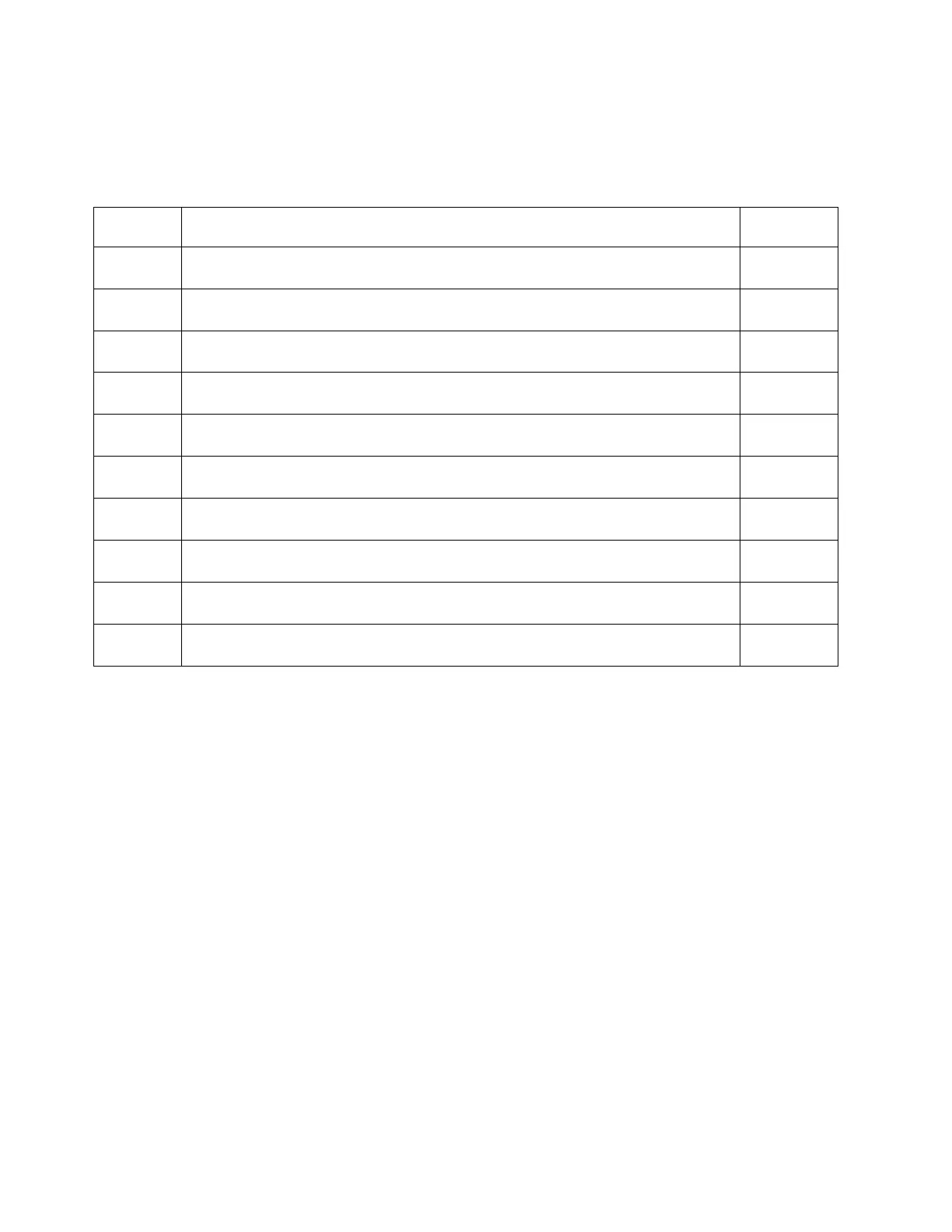
Table 139. Power cord options
Feature
code Power cord description Amps
6489 Power cord, PDU to wall, 4.3 m (14 ft), 230 V ac, 3 phase wye, Souriau UTG, IEC
60309, 3P+N+E plug
96 A (32 A x
3)
6491 Power cord, PDU to wall, 4.3 m (14 ft), 200 - 240 V ac, single phase, Souriau UTG, IEC
60309, P+N+E plug
63 A
6492 Power cord, PDU to wall, 4.3 m (14 ft), 200 - 240 V ac, single phase, Souriau UTG, IEC
60309, 2P+E plug
60 A (48 A
derated)
6653 Power cord, PDU to wall, 4.3 m (14 ft), 230 V ac, 3 phase wye, Souriau UTG, IEC
60309, 3P+N+E plug
48 A (16 A x
3)
6654 Power cord, PDU to wall, 4.3 m (14 ft), 200 - 240 V ac, single phase, Souriau UTG,
plug type 12 plug
30 A (24 A
derated)
6655 Power cord, PDU to wall, 4.3 m (14 ft), 200 - 240 V ac, single phase, Souriau UTG,
plug type 40 plug
30 A (24 A
derated)
6656 Power cord, PDU to wall, 4.3 m (14 ft), 200 - 240 V ac, single phase, Souriau UTG, IEC
60309, P+N+E plug
32 A
6657 Power cord, PDU to wall, 4.3 m (14 ft), 200 - 240 V ac, single phase, Souriau UTG,
plug type PDL plug
32 A
6658 Power cord, PDU to wall, 4.3 m (14 ft), 200 - 240 V ac, single phase, Souriau UTG,
plug type KP plug
30 A (24 A
derated)
6667 Power cord, PDU to wall, 4.3 m (14 ft), 230 - 240 V ac, 3 phase wye, PDL 56P532 96 A (32 A x
3)
Loading requirements
The power loading of the 7188 or 9188 PDU must follow these rules:
1. Total power load that is connected to the PDU must be limited to below the amperage that is listed in
the table.
2. Total power load that is connected to any one circuit breaker must be limited to 16 A (derating of
circuit breaker).
3. Total power load that is connected to any one IEC320-C13 outlet must be limited to 10 A.
Note: The load on the PDU when a dual line configuration is used is only half the total load of the
system. When you are calculating the power load on the PDU, you must include the total power load of
each drawer even if the load is distributed over two PDUs.
Loading sequence
Follow these loading sequence steps:
1. Collect power requirements for all units that are connected to the 7188 or 9188 PDU. See your server
specifications for specific power requirements.
2. Sort list by total power that is required from highest power draw to lowest power draw.
3. Connect highest power drawer to outlet 1 on circuit breaker 1.
4. Connect next highest power drawer to outlet 3 on circuit breaker 2.
5. Connect next highest power drawer to outlet 5 on circuit breaker 3.
118 Site and hardware planning
 Loading...