ic audio
EV-5000
EN
10
9. Installation
– see overview page 4 –
9.1 Power Supply
The device is designed for use with 230V AC 50 to 60 Hz mains power. Power can be switched
ON/OFF by the rear side mains power rocker switch.
A backup power providing 24V DC can be connected via a 2-pole pluggable screw terminal. The
rocker switch only breaks the mains power, not the 24V backup power. Both power sources are
monitored by the system. If during the installation run there is no backup power source connected,
the presence of the 24V DC power source is not supervised. Powering from a 24V DC source only
is not possible, since the system will generate always an error message as soon as mains power
fails, regardless what the state was during the installation run.
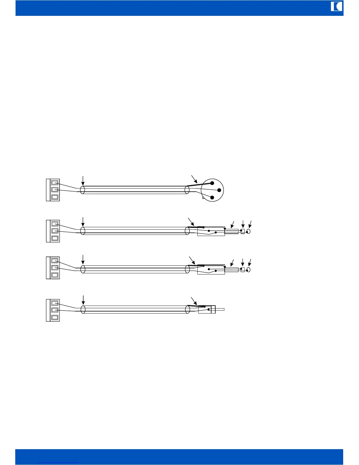
9.2 Connection of Power Amplifiers
Amplfier inputs have to be connected to the OUT CH1...OUT CH4 pluggable screw terminals, the
backup amplfier to the OUT SPARE connections. All outputs of the EV-5000 are transformer
coupled (balanced and floating) for trouble free operation. Therefore the cable shields have to be
connected at one end only. The following drawing shows some wiring for balanced and unbalanced
amplifier inputs:
These samples are valid for amplifiers, which are earthed by a 3-pole mains power cord and plug.
If all-insulated (double isolation, 2-pole mains power plug) amplfiers are used, which have also no
GND connection via a backup power supply, the shield must be connected on the EV-5000 side
(GND screw terminal) too.
The amplifier outputs (100V types only) are to be connected to the AMP IN1...AMP IN4 inputs and
SPARE AMP IN input respectively.
9.3 Connecting Speaker Lines
Speaker Lines are to be connected to the CH1 OUT...CH4 OUT terminals.
CAUTION!
For error free functioning of supervision, the minimum load has to be 10 Watts per zone at 22 kHz.
Please be aware that speaker impedances are frequency dependent, so each line has to draw
10 watts at 22 kHz not at 1 kHz. If it would be less, please connect a resistor 1 Kiloohm/10Watts in
parallel to the last speaker on the line. Maximum power must not exceed 800Watts/100V per zone.
GND + – GND + –
EV-5000 Isolate shield
2
3
1
Shield
Shield
Isolate shield
Isolate Ring or connect it with GND
GND Ring Tip
GND Ring Tip
Shield
Amplifier input XLR, bal.
Amplifier input
6.35mm Jack, bal.
Amplfier input
6.35mm Jack unbal.
Amplifier input
Cinch unbal.
GND + –
GND + –
Isolate shield
Isolate shield
Shield
 Loading...