iv Ice Bear
®
30 Unit Application Guide
List of Figures
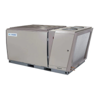
Figure 1 – Ice Bear
®
30 Unit External View ........................................................................................................ 5
Figure 2 – Ice Bear
®
30 Unit Internal View.......................................................................................................... 5
Figure 3 – Refrigerant Flow Schematic – Ice Make Mode ................................................................................... 7
Figure 4 – Refrigerant Flow Schematic – Ice Cooling Mode ............................................................................... 8
Figure 5 – Ice Bear
®
` 30 Unit (Parallel) with Ice-Ready™ Rooftop Unit .......................................................... 10
Figure 6 – Redundant (Parallel) Split System ..................................................................................................... 11
Figure 7 – Control Schematic ............................................................................................................................. 12
Figure 8 – Single Zone, Single-stage Thermostat with Economizer and Backup Condensing Unit ................... 13
Figure 9 – Single Zone, Two-stage Thermostat with Economizer and Backup Condensing Unit ..................... 13
Figure 10 – CoolData
®
Controller ...................................................................................................................... 14
Figure 11 – Ice Bear
®
30 Unit Dimensions Rear & Side Views ......................................................................... 18
Figure 12 – Ice Bear
®
30 Unit Dimensions Top View ....................................................................................... 18
Figure 13 – Ice Bear
®
30 Unit Dry Center of Gravity (Left) .............................................................................. 19
Figure 14 – Ice Bear
®
30 Unit Dry Center of Gravity (Top) .............................................................................. 19
Figure 15 – Ice Bear
®
30 Unit Wet Center of Gravity (Left) .............................................................................. 20
Figure 16 – Ice Bear
®
30 Unit Wet Center of Gravity (Top) .............................................................................. 20
Figure 17 – Ice Bear
®
30 Unit with an Ice-Ready™ Rooftop Unit .................................................................... 22
Figure 18 – Ice Bear
®
30 Unit with an Additional (Slab) Ice-Coil™ ................................................................. 23
Figure 19 – Ice Bear
®
30 Unit with an Additional (“N”) Ice-Coil™ .................................................................. 23
Figure 20 – Ice Bear
®
30 Unit with a Ductless Liquid Overfeed Coil ................................................................ 24
Figure 21 – Minimum Clearances for Unit-mounted Service Disconnect .......................................................... 25
Figure 22 – Minimum Clearances for Remotely Mounted Service Disconnect ................................................. 26
Figure 23 – Ice Bear
®
30 Unit Lifting Points ..................................................................................................... 27
Figure 24 – Recommended Spreader Bar Configuration .................................................................................... 27
Figure 25 – Minimum Recommended Concrete Pad Dimensions ...................................................................... 28
Figure 26 –Sample Precast Concrete Pad ........................................................................................................... 29
Figure 27 – Ice Bear
®
30 Unit on Structural Curb with Cap .............................................................................. 30
Figure 28 – Ice Bear
®
30 Unit Base Dimensions ................................................................................................ 31
Figure 29 – Ice Bear
®
30 Unit Base Cross Section ............................................................................................. 31
Figure 30 – Design-Day Cooling Load Profile (Example) ................................................................................. 33
Figure 31 – Sample Load Profile ........................................................................................................................ 34


 To Next Page