AQUARIUM SYSTEM
CONTROLLER
*
0-10v
MAXSPECT
TM
GYRE PUMP
GYRE PUMP
POWER SUPPLY
GYRE PUMP
PUMP
POWER SUPPLY
OPTIONAL
CONTROLLER
DO NOT MOUNT
MODULE NEAR WATER
GYRE
INTERFACE
MODULE
POWER
PUMP
2
nd
GYRE
INTERFACE
MODULE
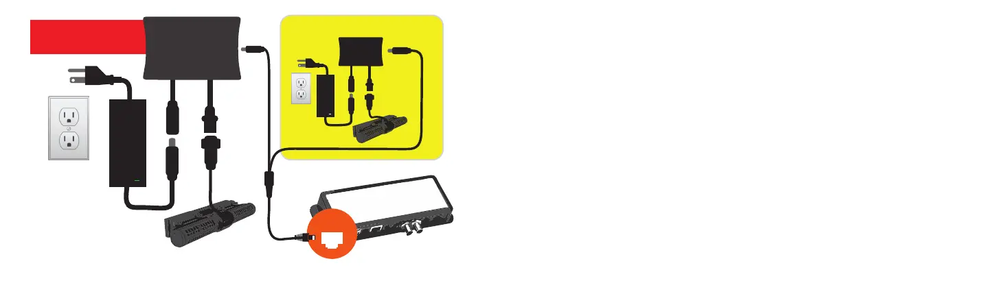
INITIAL CONNECTIONS
Unplug your Maxspect Gyre Pump’s power supply. Remove the standard Gyre controller
and re-connect the pump and power supply cable to Gyre Interface Module. Plug one
end of the included module Y cable into the side of the Gyre Interface Module and the
opposite end with the ethernet connection into an available 0-10v port on your existing
system controller.
OPERATIONAL MODE
In operational mode the Status light should always be turned off. If the controller detects
an error, such as a blocked rotor or no pump present, the status light will illuminate red
and the pump will be stopped. The red light will generally remain on for 1-2 seconds, then
it will turn off and the controller will try to restart the pump. If the error condition is gone,
the pump will continue to run. If it detects the error once more, the red light will turn on
again. The result of this is that a persistent error condition (such as a missing pump) re-
sults in a very slowly blinking red light where it is on for about 2 seconds and off for about
2 seconds (depending on the error condition).
*Aquarium system controller not included but required. This interface module is a third-party product intended to
facilitate the connection between a Maxspect Gyre
TM
Pump and a system controller.
 Loading...