LIA258-2
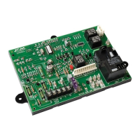
Step 2: Install the New Control
1. Ground yourself. When handling circuit board, hold it by the
edges.
2. Insert tab(s) of board into the slots of the control box (if
required).
3. Fasten circuit board with retaining screw(s). Install the
included wiring harness adapter to the three connections of
the existing furnace wiring harness.
A. The furnace harness 9-pin connector plugs into the mating
9-pin adapter harness connector.
B. The furnace harness 2-pin connector plugs into the mating
2-pin adapter harness connector.
C. The furnace harness 3-pin connector plugs into the mating
3-pin adapter harness connector.
4. Connect the other end of the included adapter harness to the
new furnace control board.
A. The 11-pin connector connects to PL1 on the furnace
control board.
B. The 2-pin connector (with 2-black wires) connects to PL2
on the furnace control board.
C. The (2) white wires connect to the 115-volt Neutral spade
connections located in front of PL1 on the new furnace
control board.
5. Connect the transformer to the new furnace control board.
A. Blue wire to SEC-2 terminal, located adjacent to the 3 amp
fuse.
B. Red wire to SEC-1 terminal, located adjacent to the 3 amp
fuse.
C. Black wire to PR-1 terminal, located adjacent to PL2.
D. White wire to one of the 115-volt Neutral spade
connections located in front of PL1.
6. Connect the black wire from the furnace auxiliary junction box
to L1 on the new furnace control board (located on the blower
enable relay).
7. Connect the white wire from the furnace auxiliary junction box
to one of the 115-volt Neutral spade connections located in
front of PL1.
8. Connect the blower motor leads to the new furnace control
board.
A. Connect the white blower motor lead to the BLW
connection within the group of 115-volt Neutral spade
connections.
B. Connect the blower motor heat tap to the blower relay
connection marked HEAT.
C. Connect the blower motor cool tap to the blower relay
connection marked COOL.
D. Connect the remaining blower motor leads to SPARE-1
and SPARE-2.
9. Connect all accessory wires.
10. For 90% furnaces, reinstall the control box assembly to the
blower deck using the screws previously removed from the
blower deck.
11. Set blower off delay jumper located on the top-center portion
of the control board. The factory default is set at 120
seconds.
12. Afx the new wiring diagram label over the existing wiring
diagram. Make sure to use the correct label for 80%
(LAPP25) or 90% (LAPP26) furnaces.
13. Do not connect the thermostat wires to the control board until
System Tests are complete.
System Tests
Step 1: Component Self Test
1. Begin component test sequence by ensuring that thermostat
is turned to OFF position and thermostat wires are
disconnected. Turn power ON and manually close the blower
door switch. With a short piece of wire, briey short TEST/
TWIN terminal to Com/24V terminal. The component test
sequence follows:
A. Status LED will ash code and will then turn ON the
inducer motor.
B. Inducer motor will run for the entire component test.
C. Hot surface ignitor will turn ON for 15 secs.
D. Blower motor heat speed will turn ON for 10 secs.
E. Blower motor cool speed will turn ON for 10 secs.
2. Repair, replace, or service any failing components from the
component self test. The gas valve is not energized during
the self test.
3. Turn power OFF.
4. Release the blower door switch.
5. Connect thermostat wires.
6. Install blower door and access door.
7. Turn power ON.
8. Turn gas ON.
Step 2: Flame Sensor Operation
Connect a DC microammeter in series with ame sensor.
Initiate a heat call. After burners ignite and stabilize, measure
ame current. Nominal ame current is between 2.0 and
3.0 microamps DC. If ame current reading is less than 2.0
microamps DC, either replace or remove and clean ame sensor
with a ne grade steel wool. When the ame current falls to 0.5
microamps DC, the furnace control will lock out.
Step 3: System Operation
1. Perform necessary safety checks. Consider ame safety, limit
switch, and vent system.
2. Operate unit through a complete call for heat cycle.
Twinning Instructions
A 3/16” quick connect terminal is provided on the ICM282 control
board for communication between another ICM282 control board
for furnace twinning.
To congure your control boards for twinning:
1. Install each control board according to the installation
instructions.
2. Connect the TWIN terminals together.
3. Connect the 24 VAC common together. (A common ground
between the two furnaces is also required.)
If the 24 VAC supplies to the control are in phase, both furnaces will
turn the blower on and off synchronously and at the same speed.
If the 24 VAC supplies are not in phase, then neither control will
respond to the thermostat commands and the status LED will ash
rapidly.
7313 William Barry Blvd., North Syracuse, NY 13212
(Toll Free) 800-365-5525 (Phone) 315-233-5266 (Fax) 315-233-5276
www.icmcontrols.com
 Loading...