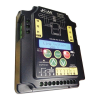
ICM455
Important Safety Information
HIGH VOLTAGE WARNING!
– Turn off power at the
main service panel before installing.
Programmable,
Three-Phase
Voltage Monitor
Phase Unbalance Protection
• Voltage Unbalance: 2-20%, adjustable
Over/Under Voltage
• Under Voltage: 2-25%, adjustable
• Over Voltage: 2-25%, adjustable
Phase Loss Protection
• Phase Loss Condition: Equals 25% of nominal for any given phase; system will
shut down and a fault will be recorded if this should occur.
Delay on Break Timer
• Control Voltage: 18-240 VAC
• Time Delay: 15 seconds to 10 minutes
Fault Interrogation Delay
• Time Delay: 0 – 15 seconds, adjustable
• Provides a delay between fault detection and system shutdown—helps to eliminate
nuisance trips and unnecessary shutdowns.
Parameters
Installation
1.Turnoffpoweratmainservicepanel.
2.Usingtwo(2)#8screws,mounttheICM455inacool,dry,easilyaccessible
locationinthecontrolpanel.
3.Connectvoltageasshownin“WiringDiagram”.Leaveexistinglineandloadside
connectionsintactonthecontactor.
4.Loadsidemonitoringisoptional(unitmaybeusedtomonitorlinesideonly).Wire
thecontactorandoptionalcontrolvoltagemonitorasshownin“SystemDiagram”.
Note:Load/line wire must be rated for 3-phase voltage rating, 20ga minimum.
5.Uponapplicationofpower,theICM455willbeonlineandwillbegintomonitor
thesystem.
Note: If voltage is not correct, see “Voltage Read Calibration” in Button
Functions section
• Terminals3and4arethecontrolsignalinputterminals.
• “ControlMode”isturnedONorOFFinsetup.
• With“ControlMode”settoON,theremustbeavoltagepresentonterminals3
and4fortherelayoutputterminals1and3toclose;thisvoltagecanbesupplied
fromathermostat,pressureswitch,etc.
• Whenthevoltageonthesesterminalsisre-applied,theunitwillnotre-energize
untilthedelayonbreak(0-10minutes)timehaselapsed.
• Useofterminals3and4isoptional;theywillbeignoredifthe“ControlMode”is
switchedtoOFF.
• Terminals1and3are“dry”,normallyopencontacts.
• Terminals1and3areclosedwhenpoweriswithinspecications.
• Terminals1and3openwhenthereisafaultcondition.
• Terminals1and3openwhenthereisalossofthecontrolsignalwith“Control
Mode”settoON.
• Auxiliaryterminalswillbeusedinfuturemodels.
Setting the Parameters
1.PressthegreenSETUPbuttontoenterthesetupmode.SetupLEDwilllight.
2.Usethe and buttonstochangeuserparameters.
3.ScrollthroughsetupbypressingandreleasingtheSETUPbutton.
4.Whenthelastparameterhasbeenset,thephaseaveragewillbedisplayedand
thesetupLEDwillautomaticallyturnoff.
Output Voltage Condition
8VDC PhaseLoss
7VDC PhaseReversal
6VDC UnderVoltage
5VDC OverVoltage
4VDC PhaseImbalance
2VDC LoadEnergized
0VDC NoPowertoUnit
Output Conditions
Button Functions
Press to return to home screen, which alternates between line voltage
and phase average.
Press arrow to scroll through and select parameter settings in Setup
Mode.
Voltage Read Calibration:
Hold both down to calibrate line voltage. Fault and setup LEDs will flash.
Usethe
and buttonstoadjust.Press SETUP to exit calibration.
Press to enter Setup Mode and select user parameters. Setup LED
illuminates when in Setup Mode.
Press to read faults. Hold for 5 seconds to clear faults and reset memory.
Fault light will blink when fault has been added to memory.
Press and hold to reset system due to system error – this will not reset
the parameters.
To turn backlight on, press any button.
Specifications
Input
• Line Voltage: 190 – 630 VAC
• Frequency: 50 – 60 Hz
• Load Side Monitoring: Optional
• Control Voltage: 18 – 240 VAC
Control Operating Temperature
• Operating Temperature: -40°F to 167°F (-40°C to 75°C)
• Storage Temperature: -40°F to 185°F (-40°C to 80°C)
LCD Operating Temperature
• Operating Temperature: -4°F to 167°F (-40°C to 75°C)
Mechanical
• Mounting: Surface mount using two (2) #8 screws
• Terminations: Screw terminals
• Dimensions: 5.5”L x 4.5”W x 1.5”H
Output
• Type: Relay, SPDT
• Voltage Range: 240 VAC at 10A max
• Frequency: 50 – 60 Hz
• Remote Monitor Voltage: 0 – 10 VDC
Typical System Diagram
NO
NC
COM
CONTROL
VOLTAGE
18-240 VAC
REMOTE
MONITORING
AUX1
AUX2 AUX3 AUX4
-
+
0-10VDC
Thermostat
or Pressure
Switch
Load
Contactor
Control
Voltage
Wiring Diagram
Contactor