1-1-32 Kamiminami, Hirano-ku, Osaka 547-0003, Japan
A-6661X-1EX Printed in China
© 2008 Icom Inc.
PANEL DESCRIPTION
CONNECTION AND OPERATION
q Connect the AC power cable of the PS-300 to an AC out-
let.
w Turn the PS-300 ON, then adjust the suitable output volt-
age.
• “ I ” : ON (Power indicator lights green)
• “O” : OFF (Power indicator goes off)
e Turn the PS-300 OFF, and make sure the equipment's
power is also OFF.
r Connect the DC power cable to the PS-300 and the
equipment's DC power input.
t Turn the PS-300 ON.
y Turn the equipment ON.
u To turn OFF the system, turn the equipment power OFF,
then the PS-300 in sequence.
OVERLOAD AND SHORT CIRCUIT PROTECTOR
The PS-300 has overload and short circuit protection circuits.
When the PS-300 is under the condition of overload or the +
and _ lines are shorted, the PS-300 limits the output current
and the overload indicator lights red. In such a case, turn OFF
the PS-300, remove the source of the problem, wait several
seconds, then turn it ON again.
V
I
–+ – +
– +
O
A
w
q
!0 !1i
e
r
t
uy o
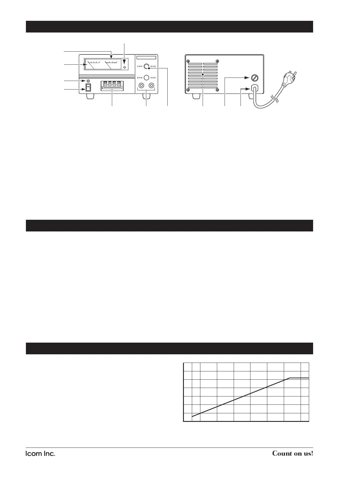
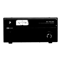
FRONT PANEL
q OVERLOAD INDICATOR
Lights red when
the PS-300 is under the condition of over-
load or the + and _ lines are shorted
.
w AMPERE METER
Shows the driving current.
e VOLTMETER
Shows the output voltage.
r POWER INDICATOR
Power indicator lights green when the PS-300 is turned
ON.
t POWER SWITCH
Turns the PS-300 power ON or OFF.
y DC OUTPUTS (Max. 3 A)
Connect DC power cables.
u DC OUTPUTS (Max. 30 A)
Connect DC power cables.
i CONTROLLER
Adjusts the DC output voltage within 1–15 V.
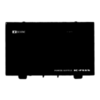
REAR PANEL
o COOLING FAN
!0 FUSE HOLDER
5 A fuse (F5AL250V) is installed.
!1 AC POWER CABLE
Connects to the AC outlet.
CURRENT CAPACITY
0
10
20
30
21 4 6 8 10 12 14
Output Voltage [V]
Output Current [A]
15
Current capacities of the PS-300 depend on their output
voltage as per the graph at right. (The graph shows typical
values for reference.)