2. Installation :
2-1. Printer Device Interconnection
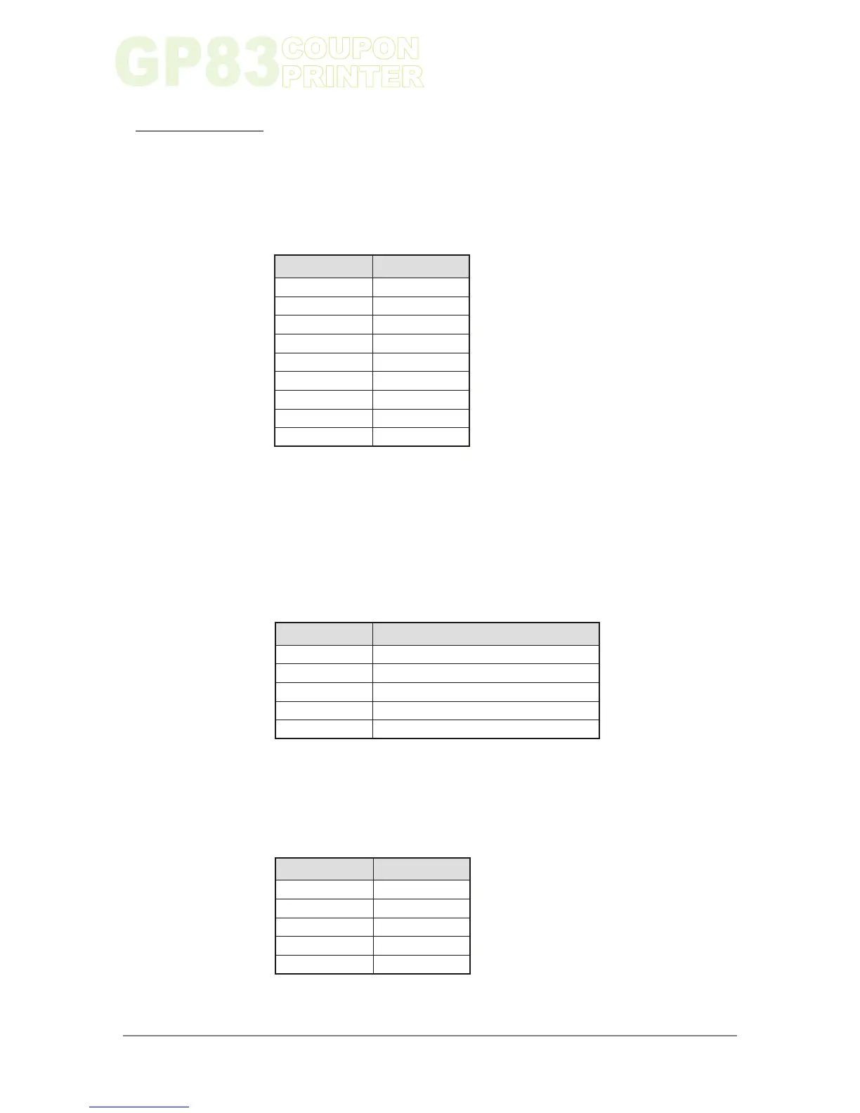
2-1-1. Power Supply Connector
2-1-2. RS232 Communication Connector
2-1-3. USB Communication Connector
Connector CN9
Power supply (Vbat) is 24V±10%
IMPORTANT NOTE:
Wires AWG26 must be used in order to avoid current losses.
PIN NUMBER
PIN NUMBER
PIN NUMBER
Connector CN7
GND
Transmit data (TxD, printer output)
Receive data (RxD, printer input)
CTS/DSR (printer input)
RTS/DTR (printer output)
Connector CN1
VBus
D-
D+
N.C
GND
SIGNAL NAME
SIGNAL NAME
SIGNAL NAME
1
1
1
GND
2
2
2
GND
3
3
3
GND
4
4
4
GND
5
5
5
GND
6
Vbat
7
Vbat
8
Vbat
9
NC
Chapter 2
7
www.ictgroup.com.tw
Table 1
Table 2
Table 3
 Loading...