Do you have a question about the Icy Box IB-1817MC-C31 and is the answer not in the manual?
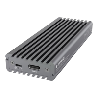
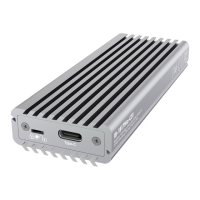
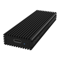
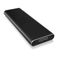
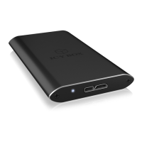
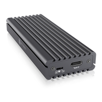
Details LED status, write protection switch, and USB connection.
Covers host computer compatibility, interfaces, and OS support.
Lists all items included in the product packaging.
Explains the enclosure's function, capacity, and applications.
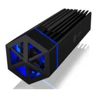
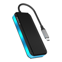
Highlights features like data transfer rates, sockets, and heat dissipation.
Advises disconnecting all cabling before beginning assembly.
Instructions for removing the front cover by unscrewing.
Instructions for carefully removing the printed circuit board.
Guide for inserting the M.2 SSD and rubber fixation.
How to push the SSD down and align fixation through PCB.
Instructions for placing the thermal pad on the M.2 NVMe SSD.
How to place and align the heat sink plate.
Guide for installing the PCB back into the housing.
Instructions for reattaching the cover and a note on write protection.
How to connect the device and initial LED status.
How write protection affects the LED and activation timing.
Safe procedures for hot-swapping the drive.
Steps required for a new SSD to be recognized.
Checks for driver installation and SSD status.
Notes on achieving USB 3.2 Gen 2 speeds and driver needs.
| Material | Aluminum |
|---|---|
| Product type | SSD enclosure |
| Product color | Gray |
| LED indicators | Yes |
| Storage drive size | M.2 \ |
| Maximum storage capacity | 2 TB |
| Supported storage drive heights | 22 mm |
| Supported storage drive lengths | 30, 42, 60, 80 mm |
| Number of storage drives supported | 1 |
| Supported storage drive interfaces | PCI Express 3.0, Serial ATA III |
| Power source type | USB |
| Chipset | RTL9210B |
| Country of origin | China |
| Data transfer rate | 10 Gbit/s |
| Cables included | USB Type-C to USB Type-C |
| USB version | 3.2 Gen 2 (3.1 Gen 2) |
| USB connector type | USB Type-C |
| USB connector gender | Female |
| Harmonized System (HS) code | 84733080 |
| Depth | 40 mm |
|---|---|
| Width | 104 mm |
| Height | 15 mm |
| Weight | 92 g |
| Cable length | 0.2 m |
| Package depth | 105 mm |
| Package width | 27 mm |
| Package height | 200 mm |
| Package weight | 213 g |