ADS-RR(SR)-FO2-DS maestro.idatalink.com
Ford F150 2013-2014
Automotive Data Solutions Inc. © 2015
4
INSTALLATION INSTRUCTIONS
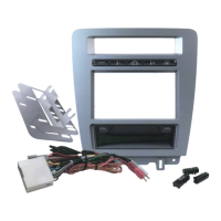
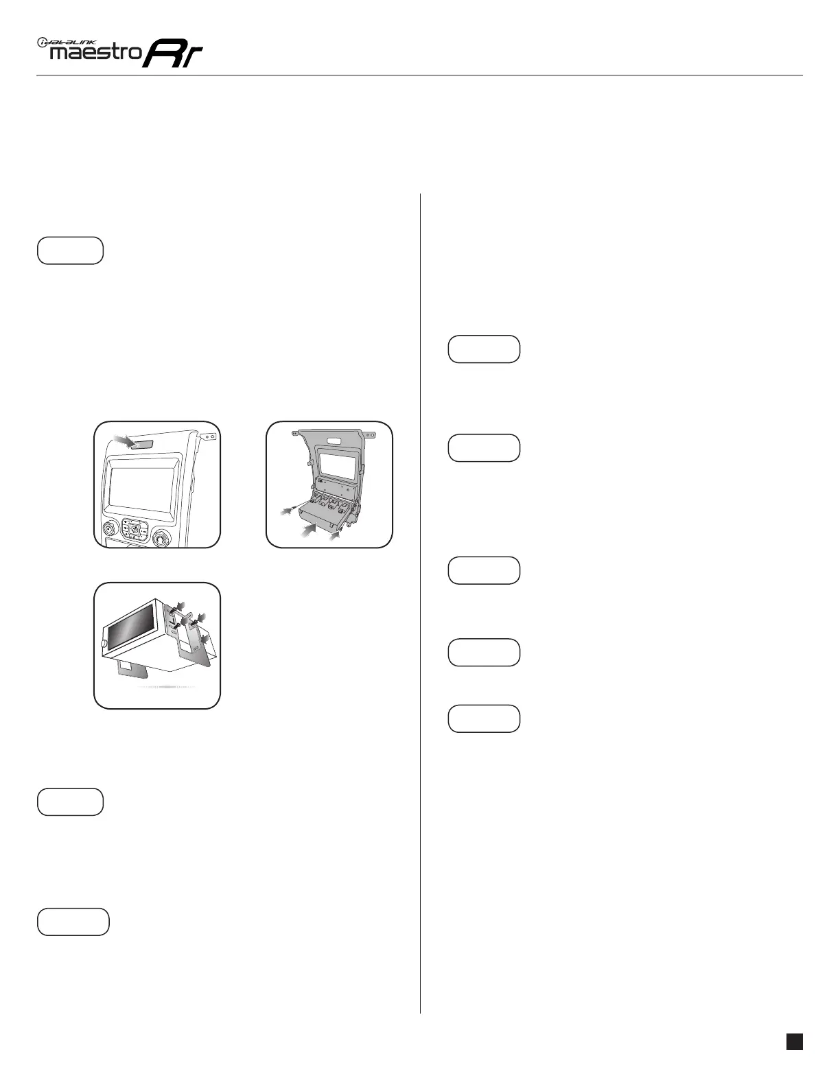
DASH KIT ASSEMBLY
STEP 8
• Unbox the K150 dash kit.
• Insert the factory traction control button into the K150 dash
kit. (2.1)
• Attach the storage pocket to the backside of the K150 dash
kit and secure it with the screws included in the kit. (2.2)
• Secure the K150 steel radio brackets to the aftermarket
radio using the screws included with the aftermarket radio.
(2.3)
CONNECTIONS (REFER TO DIAGRAM)
STEP 9
• Unbox the aftermarket radio and locate its main harness.
• Connect the wires from the aftermarket radio’s main
harness to the K150 T-harness and match the wire colors
(refer to diagram).
STEP 10
• Plug the aftermarket radio harnesses into the aftermarket
radio.
• Plug the Data cable to the data port of the aftermarket
radio (labeled iDatalink).
• Insert the Audio cable into the iDatalink 3.5 mm audio jack
of the aftermarket radio (labeled iDatalink).
NOTE:
In Pioneer radios: plug Audio cable in auxiliary input of
the radio.
• Plug the backup camera RCA cable into the aftermarket
radio (if applicable).
STEP 11
• Plug the aftermarket radio harnesses into the OBDII
connector, located under the driver side dashboard, and
run the wires up to the radio cavity.
STEP 12
• Connect the K150 T-harness to the factory radio harness.
• Plug the backup camera cable into the factory harness (if
applicable).
• Plug the HVAC cable in the factory harness.
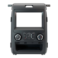
STEP 13
• Insert the radio into the dash and secure the metal
brackets with the 7mm bolts removed during disassembly.
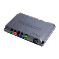
STEP 14
• Connect all the harnesses to the Maestro RR module.
STEP 15
• Connect all the harnesses to the K150 dash kit.
• Secure the K150 kit in the dash.
TROUBLESHOOTING TIPS:
• To reset the module back its factory settings, turn the key
to the OFF position then disconnect all connectors from
the module. Press and hold the module’s programming
button and connect all the connectors back to the module.
Wait, the module’s LED will fl ash RED rapidly (this may
take up to 10 seconds). Release the programming button.
Wait, the LED will turn solid GREEN for 2 seconds.
• For technical assistance call 1-866-427-2999 or e-mail
“support@idatalink.com”. Visit us at “maestro.idatalink.
com/support” and “www.12voltdata.com/forum/”
1
Fig. 2.1
Fig. 2.3
Fig. 2.2
A/C
MAX
A/C
OFF
PASS
AIRBAG
OFF
 Loading...