SERVICING
Mini Installation & Servicing 43
60 DHW FILTER AND FLOW LIMITER
REPLACEMENT
Mini C only
1 Disconnect the electrical supply.
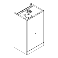
2 Remove the front panel of the case and empty the DHW
circuit.
3 Remove the flow switch A (see frame 59).
4 Unscrew the body C and extract the flow switch group.
5 To remove the filter B from the flow switch group separate
it from the threaded ring by levering it.
6 Re ---assemble in reverse order.
A --- f l o w s w i t c h
B --- f i l t e r
C--- body
Magnetic ring
Float
Spring
Flow limiter
Threaded ring
O --- r i n g
Flow limiter
The Mini C24 model is factory fitted with a 10 litre/min. flow
limiter.
The Mini C28 model is factory fitted with a 12 litre/min. flow
limiter.
The Mini C32 model is factory fitted with a 14 litre/min. flow
limiter.
Ta b l e 1 1
Nominal flow rate (litres/min)
Colour
10 Yellow
12 Brown
14 Pink
To install the threaded ring with the flow limiter:
1 Disconnect the electrical supply.
2 Remove the front panel of the case and empty the DHW
circuit.
3 Remove the flow switch A (see frame 59).
4 Remove the flow switch group (see frame 59 above)
5 Unscrew the threaded ring and remove it from the body C.
6 Extract the flow limiter.
7 Fit the correct colour coded limiter (see Table 11 above)
and screw the threaded ring tight into the body C.
8 Re ---assemble in reverse order.
SERVICING
 Loading...