Do you have a question about the Idemia MorphoAccess SIGMA Lite Series and is the answer not in the manual?
Details terminal models (Lite+, Lite) and associated card reader types (ICLASS, MULTI, PROX).
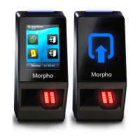
Identifies key components like LEDs, LCD screen, biometric sensor, ports, and optional features.
Lists all items included in the product packaging, such as the terminal, cables, and documentation.
Explains the terminal's role in processing access requests via biometrics, card, or PIN.
Describes the interface between the terminal and a third-party Access Controller using various protocols.
Details integration with alarms and door latches for access control systems.
Outlines the step-by-step process of access control from request to granting access.
States that fingerprints must be stored in the terminal or card for biometric checks.
Details the four access control modes (Identification, Authentication, Multifactor, Proxy) and their functions.
Lists operating and storage temperature, humidity ranges, and IP rating for the terminal.
Advises against extreme temperatures, static discharge, and specifies lighting and flammable area rules.
Suggests protective enclosures for outdoor use against weather elements impacting durability.
Details the pinout configuration for RJ-45 Ethernet and Power over Ethernet connections.
Provides the pinout and connection details for RS-485 General Purpose Input/Output.
Outlines the pin assignments for Wiegand input and output connections.
Details the wiring for power supply and tamper switch connections.
Emphasizes safety measures like using SELV connections and preventing electrostatic discharge during wiring.
Explains how power is supplied via the RJ-45 connector using PSE compliant equipment.
Specifies voltage and current requirements for external power supply and compatibility standards.
Provides a table showing voltage drop based on wire gauge and cable length for reliable power.
Warns that under- or over-powering can cause data corruption or hardware damage, voiding the warranty.
Illustrates the wiring block for RS-485 communication, showing pin connections.
Details the specific pin assignments for RS-485 communication, including TDA, TDB, and Ground.
Recommends CAT-5 UTP shielded cable and AWG 24 as the minimum wire gauge for RS-485.
Specifies the maximum number of devices per line and the total cable length for RS-485 installations.
Describes the wiring for the Ethernet terminal block, emphasizing careful connection.
Recommends category 5 shielding cable and suggests repeater units every 90m.
Explains that the terminal defaults to Static IP mode and provides factory values.
Details support for 802.11b/g standards and security protocols like WEP, WPA, WPA2.
Details the pin assignments for Wiegand data, clock, and ground connections.
Specifies the need for three-conductor wire (shielded recommended) and cable gauge.
Guides on connecting Wiegand OUT0, OUT1, and GND to the Access Control Panel.
Provides maximum cable distances based on AWG for Wiegand connections.
Notes that Wiegand output is disabled by default and requires configuration before connecting.
Explains that system administrators select or create Wiegand formats during installation.
Mentions support for the Clock & Data protocol and its wiring.
Illustrates the wiring for SDAC, including connections for a push button and door strike.
Details the relay connections required for door strike control in SDAC.
Explains the use of GPI1 and GPO1 for door contact status monitoring.
Shows the internal relay wiring, including deadbolt/door strike and push button connections.
Warns about the 1A @ 30V current limit for internal relays and the need for external relays for higher loads.
States the internal relay's design limit of 100,000 cycles and suggests external relays for more.
Emphasizes the necessity of a network link for the first configuration and maintenance.
Describes setting up a direct Ethernet connection, requiring static IP configuration.
Explains connecting via LAN, noting DHCP server availability affects automatic or static IP configuration.
Provides guidelines for IP address and network mask configuration for PC and terminals.
Details using MorphoBioToolBox to fill IP/Network mask, save to USB, and configure the terminal.
Explains how the embedded web server facilitates easy configuration and user enrolment via browser.
States that connecting to the webserver requires terminal IP address and password.
Advises deactivating the web server when it is not in use for security reasons.
Introduces MorphoBioToolBox as a dedicated application for configuring the terminal.
Provides contact information for requesting the MorphoBioToolBox software in different regions.
States full compatibility with MorphoManager application version 8.0.3 or higher.
Details compatibility with MEMS and SecureAdmin for Legacy Morpho and L1 modes.
Identifies the most useful area of the fingerprint for capture, typically the fingertip center.
Recommends using the forefinger/index first, followed by the middle and ring fingers.
Provides solutions for fingerprint image quality issues like too dark or too light.
Illustrates correct and incorrect finger placement regarding height on the sensor.
Shows the correct and incorrect angles for placing the finger on the sensor.
Demonstrates correct and incorrect finger inclination relative to the sensor surface.
Illustrates proper and improper finger rotation for optimal fingerprint capture.
Explains the meaning of different LED colors and blinking patterns for the SIGMA Lite model.
Details the screen displays and states for the SIGMA Lite+ model, including access granted/denied.
Instructs on correctly positioning the contactless card near the reader for authentication.
Explains how users enter their PIN code using the on-screen numeric keypad.
Introduces the optional Time and Attendance (T&A) feature available on SIGMA Lite+ terminals.
Explains how T&A information is added to identification/authentication records in the event log.
Describes the two function keys used by the user to specify entry or exit of a task.
Notes that this feature is exclusively available with the optional touchscreen LCD.
States the manufacturer is not responsible for non-compliance with recommendations or incorrect use.
Advises against self-repair and using non-original accessories, as they void the warranty.
Recommends regular backups for terminals used in standalone mode, especially after changes.
Recommends synchronizing time for high-precision applications and notes typical time deviation.
Provides detailed instructions for cleaning and disinfecting the terminal, especially the biometric sensor.
Lists documents related to terminal installation, mounting, and secure setup procedures.
Lists guides for terminal administration, usage, and detailed configuration parameters.
Lists specifications and interface guides for developers working with the terminal.
Information on release notes for firmware versions, detailing new features and limitations.
Provides contact information (mail and phone) for technical support across various regions.
Directs users to the website for the latest firmware, software, and document releases.
States copyright information and acknowledges registered trademarks of IDEMIA and third parties.
| Category | Touch terminals |
|---|---|
| Device Name | Idemia MorphoAccess SIGMA Lite Series |
| Ingress Protection | IP65 |
| Authentication Methods | Fingerprint, Card, Pin code |
| Fingerprint Sensor | Optical |
| Operating System | Embedded Linux |
| Connectivity | Ethernet, USB |
| Power Supply | 12V DC |
| Card technologies | MIFARE, DESFire, NFC |
| Storage Temperature | -20°C to 70°C |