or gain. All of the risers including the riser stubouts should
be properly covered with insulation. Internally mounted
chilled water piping and valves are located over the drain
pan and need not be insulated.
Any reproong requirements where risers or piping
penetrate oors or walls are the responsibility of the
installer. This work should be done only after all pressure
testing is completed. The reproong method used must
accommodate pipe expansion and contraction and the
piping must be protected from abrasion and chemical attack.
The pipe insulation also must be maintained to prevent
sweating and must be protected from wear or erosion at the
joint between the insulation and the reproong material.
When no risers are ordered for the Mega Modular unit, it is
the responsibility of the installer to make sure that a eld
supplied isolation ball valve is installed between each supply
and return piping connection to the unit. Flare ttings are
factory provided to allow connection between the ball valves
and the hoses.
Variations in oor-to-oor dimensions may require eld work
such as cutting o or extending the risers. This operation is
the responsibility of the installer. The riser joint ller material
must be selected to withstand the total operating pressure
(both static and pumping head) to which the system will be
subjected. Low temperature lead alloy solders such as “50/50”
and “60/40” are normally not suitable.
Chilled water and hot water risers should never be piped
to drain down into the condensate riser. Extensive water
damage can occur due to drain overow. Drain chilled and
hot water risers to a remote location away from the unit such
as sink, room and oor drains.
All installations should be made in compliance with all
governing codes and ordinances. Compliance with all
codes is the responsibility of the installing contractor.
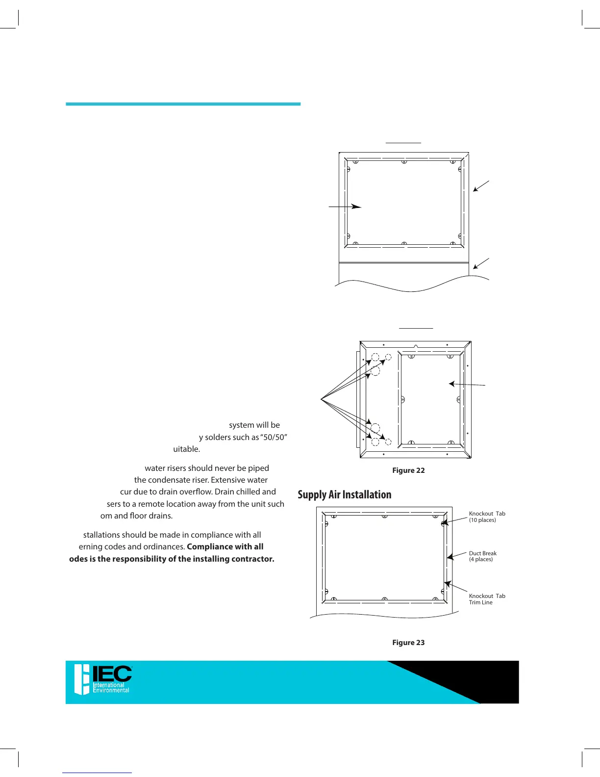
Unit Knockout Locations (Typical)
 Loading...