OPERATION
Front Panel Operation
03_10 LDX-36000 Series 31
CHAPTER 3
Indicators immediately below the display will illuminate if a limit or error has been
detected. The detection of an open circuit or voltage limit will always disable the
output.
Any error codes generated by the instrument will be shown on Display 1.
Simultaneous errors will result in only the highest priority error code being
displayed.
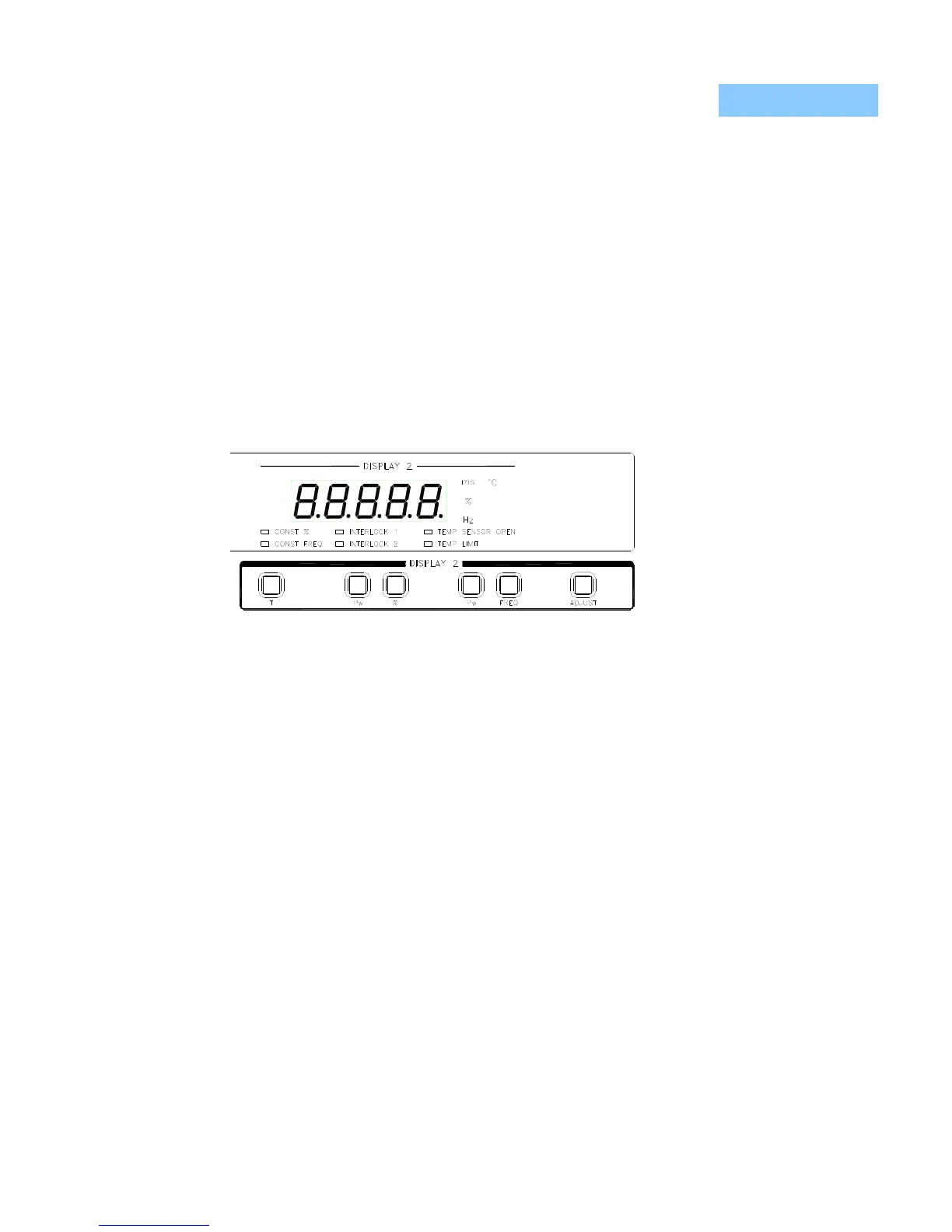
Display 2
The right-hand display, shown in Figure 3.6, shows the parameters of QCW
pulsewidth (ms), pulse rate (Hz), and duty cycle (%), along with temperature (°C)
and photodiode responsivity (mA/W - not annunciated).
In the cases where
one of the above
parameters is a
setpoint being
adjusted, the
appropriate
annunciator will flash.
Figure 3.7 Display 2
If either interlock has opened, no thermistor has been connected to the
temperature sensor inputs, or the measured temperature has exceeded the set
temperature limit, the appropriate indicator will flash. The indicators below the
display are divided into two groups, instrument mode (Const %, Const Freq) and
error indicators. If any error has been detected, the output will be disabled. This
behavior may be changed via the Output Off Register (described in detail in
Chapter 4).
 Loading...