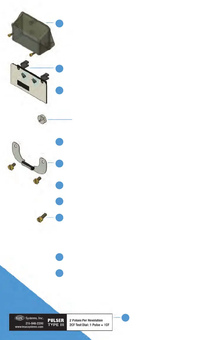
1 Detach the meter’s index cover by unscrewing
(3) llister head screws. Once detached, set the
index cover and the screws aside. The index cover
and the screws will be used in later steps.
a) If red security caps are present, tap them with a
screwdriver to break through the security cap, and
then remove the security caps with needle nose pliers.
2 Detach the meter’s index by unscrewing (2) panhead screws.
Once detached, set the index and the screws aside. The
index and the screws will be used in later steps.
3 Remove the brass meter drive by unscrewing in a
counterclockwise rotation.
a) Sometimes the meter drive requires a moderate tap to
the projected end of the toggle to knock it loose and to
begin the counterclockwise unscrewing.
b) The brass meter drive will not be re-used in later
steps, it is replaced with the supplied drive hub
assembly in step 4.
4 With pin facing outward, install the supplied drive hub
assembly onto the meter shaft. The drive hub assembly is
threaded on by screwing it onto the meter shaft clockwise.
5 Using the panhead screws from the index removal, attach
the pulser assembly. Leave the panhead screws loose for
the following step.
6 Remount the meter’s index utilizing the index’s slots onto the
panhead screws from step 5.
7 Align the mechanical index and drive hub assembly and
tighten the panhead screws.
8 Remount the meter’s index cover with llister head screws,
make sure the index seal or gasket has not been damaged.
a) Guide the pulser wires around the meter’s index to
clear any gears. Continue guiding wires through the
bottom notch or hole in the meter’s index cover. Avoid
twisting or straining the wires.
9 Insert new red security seals in index cover holes by pushing
them in rmly.
10 To test the meter’s pulse output, use a multimeter’s ohm
setting (preferably a multimeter that makes a sound or lights
up when there is continuity). Attach the leads of multimeter
to each wire from pulse output. Slowly blow air through the
inlet side of the gas meter. As the gas meter’s 2CF test dial
rotates, multimeter will alert you of continuity. Every full
revolution of the test dial will create 2 pulses.
11 Afx IMAC PULSER Type
III label to meter for visual
identication.
Installing the IMAC PULSER TYPE III:
 Loading...