-6- -7-
To REMOTE TURN-ON
from HEAD UNIT
GROUND
To BATTERY
Sub woofer Speaker
+
Power
Batt Rem
Gnd
Sub
CH 1 CH 2
Bridged
CH 3 CH 4
Fuses
Ch1
SPEAKER
Ch2
SPEAKER
Ch3
SPEAKER
Ch4
SPEAKER
5 Channel Amplifiers LK 705
To REMOTE TURN-ON
from HEAD UNIT
GROUND
To BATTERY
Sub woofer Speaker
+
Power
Batt Rem
Gnd
Sub
CH 1 CH 2
Bridged
CH 3 CH 4
Fuses
Ch1-2
SPEAKER
Ch3-4
SPEAKER
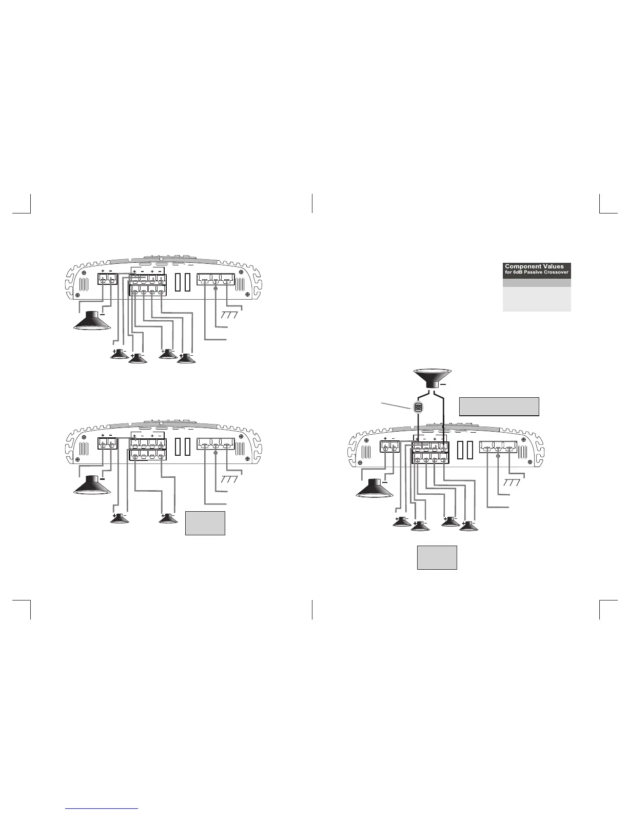
Speaker wiring
Bridged speaker wiring
To REMOTE TURN-ON
from HEAD UNIT
GROUND
To BATTERY
Sub woofer Speaker
+
Power
Batt Rem
Gnd
Sub
CH 1 CH 2
Bridged
CH 3 CH 4
Fuses
Ch1
SPEAKER
Ch2
SPEAKER
Ch3
SPEAKER
Ch4
SPEAKER
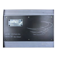
Tri-mode speaker wiring
+
LOW PASS
FILTER (INDUCTOR)
SPEAKER
IMPEDAN CE
4 - 8 OHMS!
SPEAKER
IMPEDAN CE
4 - 8 OHMS!
SUBWOO FER MINIMU M
IMPEDAN CE 8 OHMS!
Tri-Mode Speaker Wiring Two Channel Amplifier
Component ValuesComponent Values
for 6dB Passive Crossoverfor 6dB Passive Crossover
Frequency Inductor Capacitor
80Hz 7.5mH 470uF
100Hz 6.5mH 330uF
120Hz 5.5mH 330uF
150Hz 4mH 220uF
Tri-Mode Operation is a unique feature which allows a two channel amplifier to drive a sub-woofer operated
in MONO mode, while simultaneously driving full range speakers in STEREO.
Connect the NEGATIVE SPEAKER TERMINAL to the
RIGHT CHANNEL NEGATIVE AMPLIFIER TERMINAL.
Connect the POSITIVE SPEAKER TERMINAL to the
LEFT CHANNEL POSITIVE AMPLIFIER TERMINAL.
Connect the NEGATIVE SPEAKER TERMINAL to the
RIGHT CHANNEL NEGATIVE AMPLIFIER TERMINAL.
Connect the POSITIVE SPEAKER TERMINAL to the
LEFT CHANNEL POSITIVE AMPLIFIER TERMINAL.
To engage the amplifier in this mode, place the Crossover (Subwoofer)
switch in the FULL position. Use a 100V non-polar capacitor for a high
pass crossover and a wire coil inductor to block high frequencies from
the subwofer, as shown in the figure below. Pls review the table below
for inductor and capacitor component value, to determine the desired
crossover frequencies