IMSAI 8080 System
General Assembly and
Test Instructions
With the Power Supply checked out and operating
properly, the rest of the system is ready to
be tested. The MPU board should be inserted in the
slot behind the front panel with the flat cable
inserted into the socket in the upper right hand
corner of the MPU board before the board is fully
seated.
The memory board should then be inserted in the
third slot. While it is not necessary that the
first memory board be addressed beginning at po
sition 0, it is normally expected and the rest of
this section will assume that the memory board
jumpers were wired according to the directions
in the User Guide section of the RAM-4A board for
addressing the board at_0.
The slots in the Mother board are not unique and
if a larger version (e.g., 22 slot) was ordered
with more edge connectors, the boards need not be
plugged into the second and third slot as directed
but may be plugged into any slots.
SYSTEM FUNCTIONAL TEST
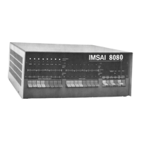
When the boards are installed, the machine is
ready to test. Turn the power on with the front
panel rocker switch and depress the RUN/STOP
switch momentarily to STOP position and release.
The WAIT light should be on and the RUN and HOLD
lights should be off, with the other lights in
various states at this time. Raise the RESET
switch momentarily to the RESET position and
release. A H the lights on the bottom row in
the ADDRESS BUS section should b e, indica
ting that the program counter is set to loca
tion 0. The WAIT light should still be on with
the RUN and HOLD lights off. The DATA BUS lights
may show various random bits on and the STATUS
byte should have three lights on: MEMR, Ml,
and WO. With all 16 ADDRESS switches in the down
or 0 position, the EXAMINE/EXAMINE NEXT switch