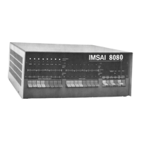
IMSAI 8080
General Assembly and
Test Instructions
The Status Byte will again have MEHR ,Ml, and WO lights •/
lit and the others off. When the single step switch is
operated once again, the processor is permitted to
complete the cycle during which it reads in the output
instruction and begin the next cycle during which it will
read the address of the output device. Since it is reading
this address from the next memory position, (memory
position 3), the address bus will have bits one and 0 -<on
and the others off. The Data Bus. will have all lights on
indicating the bit pattern we stored in memory position 3.
The status bit will show MEMORY READ and.WRITE OUT lights
on, and the Ml light is off at this time, indicating that
this is not an instruction fetch cycle, but rather it is
one of the cycles required to execute the last instruction
fetched-in this case, reading the address to which the
data will be output. When the SINGLE STEP switch is
operated once again, the processor is permitted to
complete the cycle of reading the output address in and
begin the next cycle which is the output operation.
The output operation looks similar to the input in that
the address of the output device appears in both the
upper and lower half of the Address Bus, (again in this
case lighting all the lights), and the data being output
appears in^-the Data Bus , which should show the pattern
previously set in the left hand group of switches.
Since the data is being output from the accumulator in
the processor where it was previously stored in the input
instruction, it will not be affected by moving the
switches in the left hand group at this time. The
Status Byte shows the MEMR light off at this time and
shows the out light on indicating that the processor
is executing an output instruction. The WO light is
off indicating that the processor’s WRITE strobe is
active. If the SINGLE STEP switch is operated once more,
it will permit the processor to complete the WRITE
operation and begin the next cycle. At this time, the
PROGRAMMED OUTPUT lights at the top left of the panel,
should be lit according to the complement of the pattern
that was set in the switches. That is, for each switch
that was set in the up position, the light will be out,
and each switch that was set in the down position, the
corresponding light will be on.
Since the processor has completed the output instruction
the next cycle is used to fetch the next instruction to
be executed, which it will read from memory position 4.
In memory position 4 we had stored the jump instruction
 Loading...