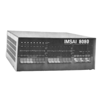
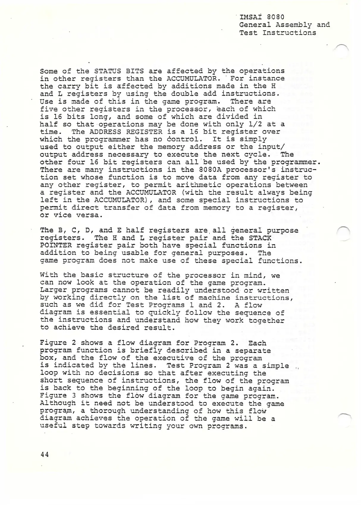
IMSAI 8080
General Assembly and
Test Instructions
Some of the STATUS BITS are affected by the operations
in other registers than the ACCUMULATOR. ' For instance
the carry bit is affected by additions made in the H
and L registers by using the double add instructions.
Use is made of this in the game program. There are
five other registers in the processor, each of which
is 16 bits long, and some of which are divided in
half so that operations may be done with only 1/2 at a
time. The ADDRESS REGISTER is a 16 bit register over
which the programmer has no control. It is simply
used to output either the memory address or the input/
output address necessary to execute the next cycle. The
other four 16 bit registers can all be used by the programmer.
There are many instructions in the 8080A processor's instruc
tion set whose function is to move data from any register to
any other register, to permit arithmetic operations between
a register and the ACCUMULATOR (with the result always being
left in the ACCUMULATOR), and some special instructions to
permit direct transfer of data from memory to a register,
or vice versa.
The B, C, D, and E half registers are,all general purpose
registers. The H and L register pair and the STACK
POINTER register pair both have special functions in
addition to being usable for general purposes. The
game program does not make use of these special functions.
With the basic structure of the processor in mind, we
can now look at the operation of the game program.
Larger programs cannot be readily understood or written
by working directly on the list of machine instructions,
such as we did for Test Programs 1 and 2. A flow
diagram is essential to quickly follow the sequence of
the instructions and understand how they work together
to achieve the desired result.
Figure 2 shows a flow diagram for Program 2. Each
program function is briefly described in a separate
box, and the flow of the executive of the program
is indicated by the lines. Test Program 2 was a simple ,,
loop with no decisions so that after executing the
short sequence of instructions, the flow of the program
is back to the beginning of the loop to begin again.
Figure 3 shows the flow diagram for the game program.
Although it need not be understood to execute the game
program, a thorough understanding of how this flow
diagram achieves the operation of the game will be a
useful step towards writing your own programs.
44