Do you have a question about the IndigoVision 10-Channel Rack and is the answer not in the manual?
Explains the formats used for safety notices in the guide, including warning, caution, and notice.
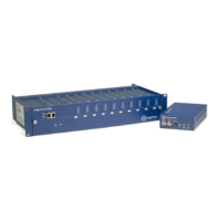
Details the components and purpose of the 10-Channel Rack, including its chassis and cards.
Describes the features and functionality of the Network Switch Card, including its uplink ports.
Explains the capabilities of Transmitter Cards for digitizing and transmitting video streams over IP.
Details the function of Receiver Cards for decoding and rendering video streams from a transmitter.
Lists prerequisites and checks required before starting the installation of the 10-Channel Rack.
Guides users through the steps required for IP configuration of the 10-Channel Rack and its cards.
Provides instructions to reset network security information and IP values to their original factory defaults.
Explains how to set up network redundancy using Spanning Tree Protocol for reliable connectivity.
Details the dual power supply connectors that enable redundant power for continuous operation.
Outlines steps to configure alarms in Control Center for power supply failures to the 10 Channel Rack.
Describes the pin configurations for BNC and RS232 serial connectors on the rack and cards.
Lists the serial port parameters required for establishing a console connection to the rack.
Shows wiring diagrams and pinouts for RS232 based PTZ and alarm control interfaces.
Details the wiring diagrams and pinouts for RS422 based PTZ and alarm control interfaces.
Explains the audio connector mapping and settings for mono/stereo input/output configurations.
Provides the physical dimensions, weight, finish, and construction details of the 10-Channel Rack.
Details the power consumption figures for the 8000 and 9000 series transmitter/receiver cards.
Lists detailed technical specifications for transmitter and receiver cards, including video and audio.
Lists the compliance standards and regulatory approvals for the 10-Channel Rack.
Explains how to connect external trigger sources to the device via binary inputs.
Details connection requirements and logic levels for input voltages below 24Vdc.
Explains the need for external resistors for input voltages exceeding 24Vdc and calculation method.
Describes the electronic switching of Rx.1 and Rx.2 binary ports controlled by software applications.
Describes the LEDs on VPxxx series interface cards and their operational meanings.
Explains the LEDs on the Network Switch Card and their status indications.
| Brand | IndigoVision |
|---|---|
| Model | 10-Channel Rack |
| Category | Racks & Stands |
| Language | English |