5 | Installation and removal INFICON
10 / 20 BM1000-Operating-Instructions-jiqb10en1-06-(1901)
5 Installation and removal
NOTICE
Install the bus module so that you can always easily disconnect the cable to the leak
detector.
5.1 Mount the bus module and the DIN-TS35 top
hat rail
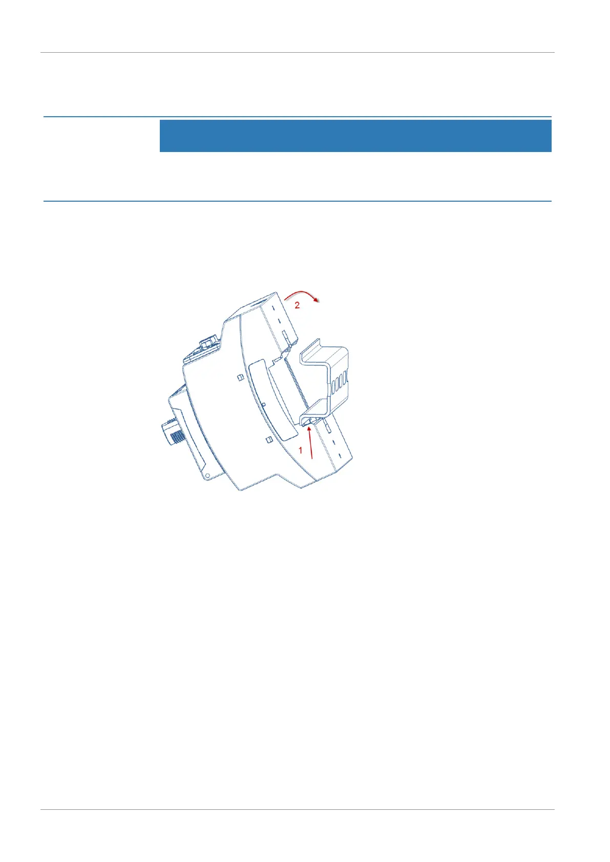
Fig.2:
Mounting of bus module
1. Hook device on top hat rail at bottom.
2. Press device onto top hat rail at top.
5.2 Establish connections
Connect the bus module with the leak detector
The bus module communicates via data cable with the leak detector and is supplied
with voltage by the data cable.
ü The device must be supplied with a circuit that meets the requirements of "Energy-
limited circuits" of DIN EN 61010-1 (VDE 0411-1).
ü INFICON data cable
1
Connect the bus module (connection LD) via the data cable with the leak
detector.
 Loading...