Bayard-Alpert Pirani Gauge
BPG400
BPG400-SD
BPG400-SP
BPG400-SR
Instruction Sheet
Incl. EC Declaration of Conformity
tima03e1-c (2010-04)
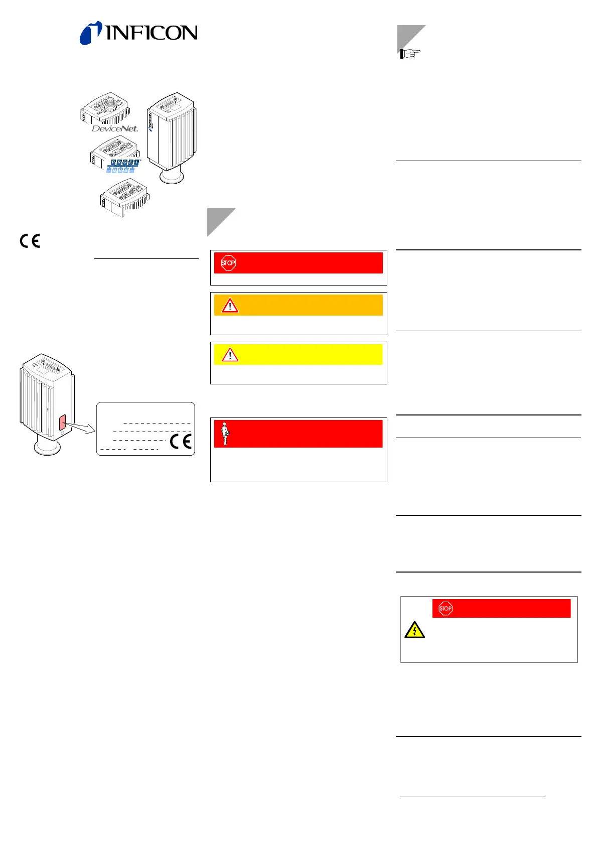
Product Identification
In all communications with INFICON, please specify the in-
formation given on the product nameplate. For convenient
reference copy that information into the space provided
below.
Model:
PN:
SN:
V W
INFICON AG, LI-9496 Balzers
Validity
This document applies to products with the following part
numbers (PN):
BPG400 (
without display)
353-500
(DN 25 ISO-KF)
353-502
(DN 40 CF-R)
BPG400
(with display)
353-501
(DN 25 ISO-KF)
353-503
(DN 40 CF-R)
BPG400-SD (with DeviceNet interface and switching functions)
353-507
(DN 25 ISO-KF)
353-508
(DN 40 CF-R)
BPG400-SP
(with Profibus interface and switching functions)
353-505
(DN 25 ISO-KF)
353-506
(DN 40 CF-R)
BPG400-SR (with RS485 interface and switching functions)
353-509
(DN 25 ISO-KF)
353-513
(DN 40 CF-R)
The part number (PN) can be taken from the product name
plate.
If not indicated otherwise in the legends, the illustrations in
this document correspond to the gauge with part number
353-500. They apply to the other gauges by analogy.
We reserve the right to make technical changes without prior
notice.
All dimensions in mm.
Intended Use
The BPG400, BPG400-SD, BPG400-SP and BPG400-SR
gauges have been designed for vacuum measurement of
gases in the pressure range of 5×10
-10
… 1000 mbar.
They must not be used for measuring flammable or combusti-
ble gases in mixtures containing oxidants (e.g. atmospheric
oxygen) within the explosion range.
The gauges can be operated in connection with the VGC103
or VGC40x Vacuum Gauge Controller or with another in-
strument or control device.
Functional Principle
Over the whole measuring range, the gauge has a
continuous characteristic curve and its measuring signal is
output as logarithm of the pressure.
The gauge functions with a Bayard-Alpert hot cathode ioni-
zation measurement system (for p < 2.0×10
-2
mbar) and a
Pirani measurement system (for p > 5.5×10
-3
mbar). In the
overlapping pressure range of 2.0×10
-2
… 5.5×10
-3
mbar, a
mixed signal of the two measurement systems is output. The
hot cathode is switched on by the Pirani measurement sys-
tem only below the switching threshold of 2.4×10
-2
mbar (to
prevent filament burn-out). It is switched off when the pres-
sure exceeds 3.2×10
-2
mbar.
Trademark
DeviceNet™ Open DeviceNet Vendor Association, Inc.
Safety
Symbols Used
DANGER
Information on preventing any kind of physical injury.
WARNING
Information on preventing extensive equipment and en-
vironmental damage.
Caution
Information on correct handling or use. Disregard can lead
to malfunctions or minor equipment damage.
Personnel Qualifications
Skilled personnel
All work described in this document may only be carried
out by persons who have suitable technical training and
the necessary experience or who have been instructed by
the end-user of the product.
General Safety Instructions
• Adhere to the applicable regulations and take the ne-
cessary precautions for the process media used.
Consider possible reactions with the product materials.
Consider possible reactions (e.g. explosion) of the process
media due to the heat generated by the product.
• Adhere to the applicable regulations and take the ne-
cessary precautions for all work you are going to do and
consider the safety instructions in this document.
• Before beginning to work, find out whether any vacuum
components are contaminated. Adhere to the relevant
regulations and take the necessary precautions when
handling contaminated parts.
Communicate the safety instructions to all other users.
Liability and Warranty
INFICON assumes no liability and the warranty becomes null
and void if the end-user or third parties
• disregard the information in this document
• use the product in a non-conforming manner
• make any kind of changes (modifications, alterations etc.)
to the product
• use the product with accessories not listed in the product
documentation.
The end-user assumes the responsibility in conjunction with
the process media used.
Gauge failures due to contamination or wear and tear, as well
as expendable parts (filament), are not covered by the
warranty.
Technical Data
In some points, the technical data of BPG400-SD,
BPG400-SP and BPG400-SR differ from those of
BPG400, which are given below (→ "Technical
Data" in [1] and [2]).
Measuring range
(air, O
2
, CO, N
2
)
5×10
-10
… 1000 mbar
continuous
Accuracy 15% of reading in the range
of 1×10
-8
… 10
-2
mbar
(after 5 min. stabilization)
Repeatability 5% of reading in the range of
1×10
-8
… 10
-2
mbar
(after 5 min. stabilization)
Emission
Switching on threshold
Switching off threshold
2.4×10
-2
mbar
3.2×10
-2
mbar
Emission current
p ≤ 7.2×10
-6
mbar
7.2×10
-6
mbar < p
< 3.2×10
-2
mbar
5 mA
25 µA
Emission current switching
25 µA ⇒ 5 mA
5 mA ⇒ 25 µA
7.2×10
-6
mbar
3.2×10
-5
mbar
Degas
Current (p <7.2×10
-6
mbar)
≈16 mA (P
degas
≈4.0 W)
Control input signal 0 V/24 V, high active
Duration <3 min, followed by
automatic stop
In degas mode, the BPG400 keeps supplying pressure
readings, the tolerances of which can be higher than
during normal operation.
Output signal
(measuring signal)
0 … +10 V
Measuring range 0.774 … 10 V
(5×10
-10
… 1000 mbar)
Voltage vs. pressure logarithmic,
0.75 V/decade
Error signal (→ [1]) ≈0.3 V (hot cathode error)
≈0.5 V (Pirani error)
Minimum load impedance
10 kΩ
Gauge identification
42 kΩ between Pin 10 and
Pin 5 (gauge cable)
RS232C interface
Data rate
Data format
Connector
9600 Baud
binary
8 data bits
one stop bit
no parity bit
no handshake
→ "Power Connection"
Further information on the RS232C interface → [1]
Display panel (353-501,
353-503)
LCD matrix, 32×16 pixels,
with background illumination
Dimensions 16.0 mm × 11.2 mm
Pressure units mbar (default),
Torr, Pa (Selecting the
pressure unit → [1])
Supply
DANGER
The gauge must only be connected to power
supplies, instruments or control devices that
conform to the requirements of a grounded pro-
tective extra-low voltage (SELV). The connection
to the gauge has to be fused
1)
.
Voltage at gauge 24 VDC (20 … 28 VDC)
(ripple ≤2 V
pp
)
2)
Power consumption
Standard
Degas
Emissions start (200 ms)
≤0.5 A
≤0.8 A
≤1.4 A
Fuse required
1)
≤1.25 AT
Power consumption ≤16 W
1)
INFICON controllers fulfill these requirements.
2)
Consider the voltage drop on the sensor cable.
RS485
Artisan Technology Group - Quality Instrumentation ... Guaranteed | (888) 88-SOURCE | www.artisantg.com
 Loading...
