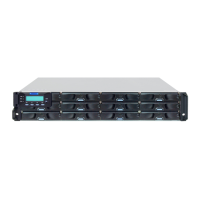
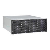
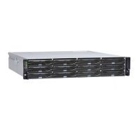
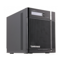
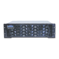
2-16 Chapter 2: Hardware installation
5. To secure the controller to the chassis, fasten two retention screws to the controller’s mounting
holes under the ejection levers.
Ejection lever Ejection lever
Mounting hole Mounting hole
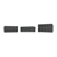
2.3 Connections
This section details the connection procedures of DS 3000 system to the expansions, power source,
connection status, topologies, and other connection congurations.
2.3.1 General considerations in connecting devices
When selecting the number of hard drives to assemble a logical drive, the host channel bandwidth
and the performance of each drive must be considered. It is a good practice that you calculate the
performance against the host port bandwidth when designing an application topology.
For example, if eight drives are included in a logical drive and is associated with a host ID (LUN
mapping), the combined performance of this logical drive must estimate the channel bandwidth. If two
6-drive logical arrays are associated with two IDs residing in a single host channel, there may be a
trade-off with the performance.
If your system comes with a total of eight or more host ports, we recommend that you use more disk
drives to an expansion so that you can create a host-port that corresponds to 6-member logical drives
(RAID 5) or 8-member logical drives (RAID 6). These logical drives bring up the bandwidth of each host.
You must also take note of these considerations:
• A spare drive that carries no data stripes and does not contribute to disk-level performance. For
performance data information of your hard drive, refer to its documentation.
• Disk drives in the same logical array must have the same capacity, but it is preferred that all drives
in the chassis have the same capacity.
• Disk drives in the same logical drive must have the same capacity, but it is preferred that all disk
drives in a chassis have the same capacity. Tiered storage conguration is supported in this setup.
However, you must not include both SAS and SATA drives in a logical drive.
• A spare drive must have a minimum capacity equivalent to the largest drive that needs
replacement. If the capacity of the spare drive is less than the capacity of the drive to be replaced,
the controller will not proceed with the failed drive rebuild.
• When rackmounting, leave enough space for the cables. DO NOT bend them to a diameter of less
than 76 mm (3 inches).
 Loading...