Do you have a question about the Infortrend EonStor S12S-R1032 and is the answer not in the manual?
| Brand | Infortrend |
|---|---|
| Model | EonStor S12S-R1032 |
| Category | Network Storage Server |
| Language | English |
Specifies that the equipment is intended for restricted access locations only.
Warns about electric shock hazards and restricts access to trained personnel.
General guidelines for safe handling, installation, and operation of the subsystem.
Emphasizes the importance of proper airflow clearance for ventilation and cooling.
Recommendations for preventing electrostatic discharge damage during module handling.
General warning about potential equipment damage or personal injury.
Guidance on obtaining and applying software and firmware updates.
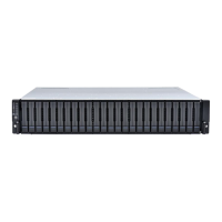
Introduces the EonStor SAS-to-SAS RAID subsystem series.
Describes the 2U chassis, its front and rear sections, and rackmount options.
Describes the function of the RAID controller module in processing I/O and parity.
Describes the LCD panel, its buttons, and access to firmware functions.
Describes the drive trays for 3.5-inch SAS/SATA drives, their LEDs, and locks.
Describes the RAID controller module, its components, and handling precautions.
Illustrates and describes the LEDs, SAS ports, and buttons on the controller faceplate.
Details the SAS host ports, their specifications, and cabling considerations.
Explains how to use the restore default button for firmware defaults.
Lists essential procedures before using the restore default button.
Step-by-step guide on operating the restore default button.
Describes the redundant, hot-swappable PSUs and their location.
Describes the redundant dual-fan cooling modules and their intelligent dual-speed operation.
Details the monitoring methods including I2C bus, proprietary service, and LEDs.
Discusses audible alarms triggered by component failures or threshold breaches.
Details the ability to exchange components while the subsystem is online.
Lists the specific components that are hot-swappable.
Introduces the chapter on installing hard drives and drive trays into the subsystem.
Lists essential requirements before starting the hardware installation process.
Provides detailed safety instructions for installation and handling.
Concerns regarding ambient temperature, openings, and grounding when rack-mounting.
Steps to prevent ESD damage during installation.
Pre-installation checks and understanding of port configurations.
Outlines the sequence of steps for a smooth installation process.
Instruction to unpack and confirm all components.
Guidance on installing the subsystem into a rack or cabinet.
Procedure for installing purchased SAS or SATA-II hard drives.
A visual flowchart to guide the installation steps.
Instructions for mounting the enclosure in a 19-inch rack cabinet.
Factors to consider when selecting and installing hard drives.
Step-by-step guide for installing a hard drive into a drive tray.
Instructions for installing drive trays into the subsystem enclosure.
Guidelines and checklist for powering on the subsystem.
Pre-power-on checks for memory, BBU, drives, cables, and ambient temperature.
Steps for powering on expansion JBODs and the RAID subsystem.
Provides general advice and precautions for component replacement.
Reiterates that most major components are hot-swappable.
Warning about the delicacy of docking connectors and pins.
Points to consider before replacing a controller module, including DIMMs and BBU module.
Step-by-step instructions for removing a controller module.
Step 4: Press levers to ease the controller module out.
Procedure for replacing a failed controller module with a new one.
Step 2 for installation: Align and gently slide in the replacement controller.
Explains the purpose of the BBU and when it needs replacement.
Step-by-step instructions for replacing a BBU unit.
Step 2: Align and push the replacement BBU into the slot.
Step 3: Fasten the retention screw to secure the BBU.
Details the redundant PSUs, PSU bracket, and immediate replacement requirement.
Instructions for replacing a faulty PSU, including warnings.
Step 4: Remove the PSU module by pulling the extraction handle.
Step 6: Insert the replacement PSU module into the chassis.
Step 7: Secure the PSU by fastening the retention screw.
Steps to replace a cooling module if it fails.
Overview of hard drive maintenance, hot-swappable trays, and removal precautions.
Step-by-step instructions for replacing a hard drive.
Emphasizes careful handling of fragile hard drives.
Step 6: Install the replacement hard drive, referring to Section 2.8.