8
trapuls – EtherCAT® Fieldbus Interface
Chapter 3 – Electrical installation
Chapter 3 - Electrical installation
3.1 - CONNECTORS
On the XtrapulsGem EtherCAT® extension board, the EtherCAT® fieldbus connectors E3 and E4 are located on
the front panel.
On the XtrapulsPac drive, the EtherCAT® fieldbus connectors X6 and X7 are located on the top of the drive.
3.1.1 "IN" CONNECTOR: E3 (XTRAPULSGEM ETHERCAT® EXTENSION BOARD), X6 (XTRAPULSPAC)
PIN SIGNAL DESCRIPTION
1 Tx Data+ Differential signals
2 Tx Data-
3 Rx Data+ Differential signals
6 Rx Data-
Others Reserved
3.1.2 "OUT" CONNECTORS: E4 (XTRAPULSGEM ETHERCAT® EXTENSION BOARD), X7 (XTRAPULSPAC)
PIN SIGNAL DESCRIPTION
1 Tx Data+ Differential signals
2 Tx Data-
3 Rx Data+ Differential signals
6 Rx Data-
Others Reserved
3.2 - INDICATORS
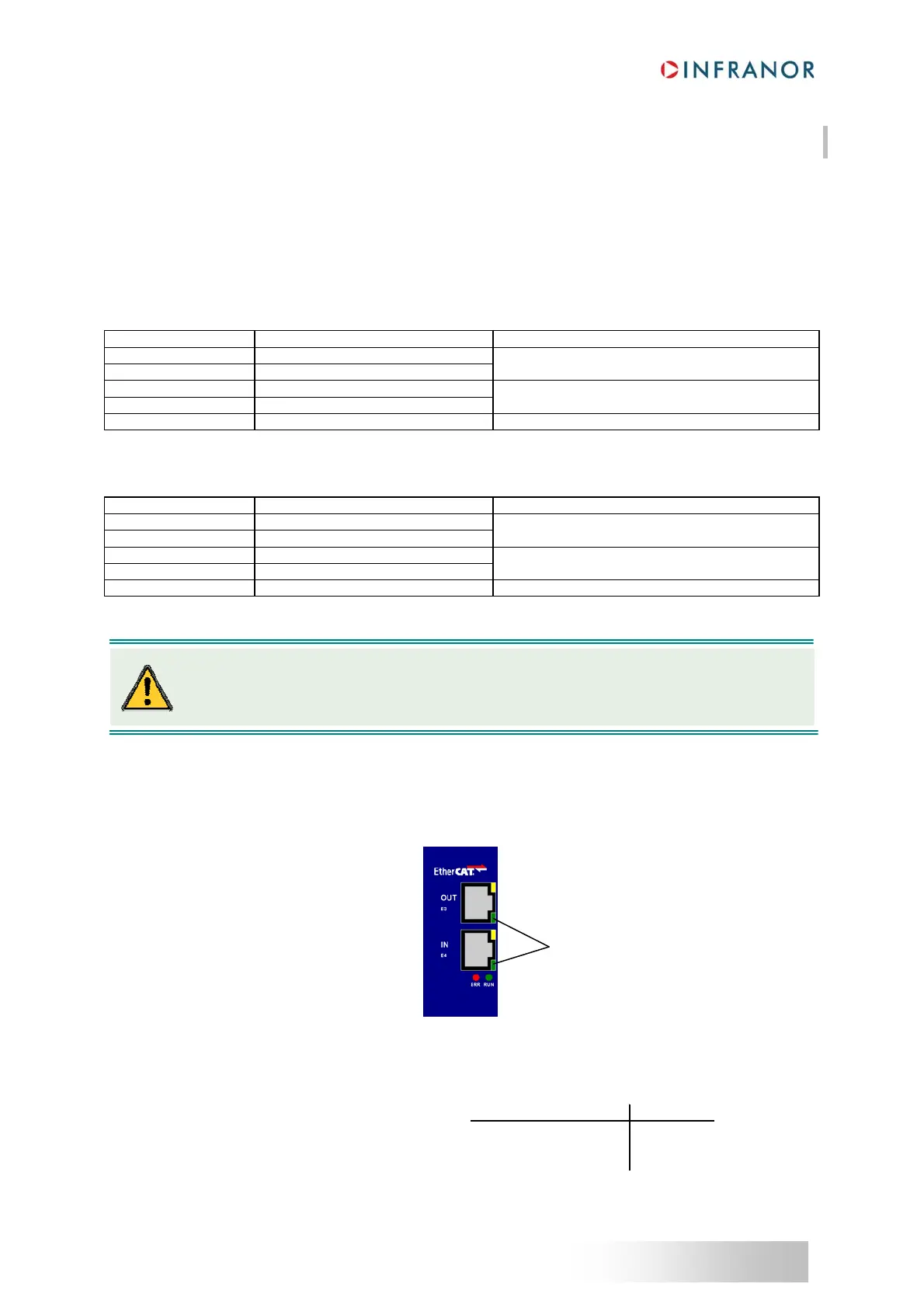
Four LEDs are available for quick diagnosis purposes. On the XtrapulsGem EtherCAT® extension board, the four
LEDs are located according to following figure:
3.2.1
- LINK/ACTIVITY INDICATORS
These two LEDs are integrated in RJ-45 sockets.
Label name Color Function
Link Activity LED coding
L/A IN Green
Link and activity on the IN port
Yes No On
L/A OUT Green
Link and activity on the OUT port
Yes Yes Flickering
No (Not Applicable) Off
Link/Activity indicators
On each EtherCAT
®
slave, the incoming cable should always be connected to the “IN” RJ-45
socket and the outcoming should also be connected to the "OUT" RJ-45 socket.
 Loading...

