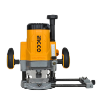
1. Wing bolt (A)
2. Guide holder
3. Fine adjusting screw
4. Wing bolt (B)
5. Wing bolt (C)
6. Trimmer guide
7. Guide roller
Install the trimmer guide on the guide holder with the wing
bolt (B). Insert the guide holder into the holes in the tool base
and tighten the wing bolt (A). To adjust the distance between
the bit and the trimmer guide, loosen the wing bolt (B) and
turn the fine adjusting screw (1.5 mm or 1/16” per turn).
When adjusting the guide roller up or down, loosen the wing
bolt (C). After adjusting, tighten all the wing bolts securely.
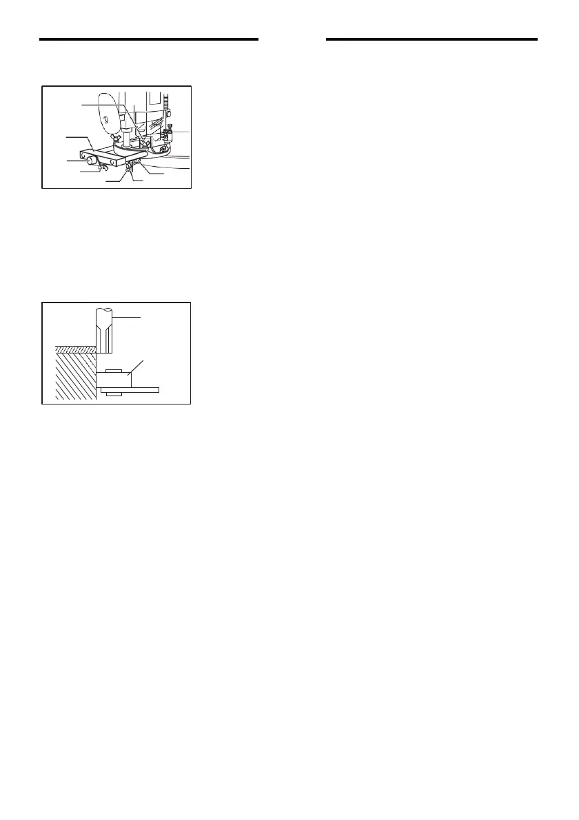
When cutting, move the tool with the guide roller riding the
side of the workpiece.
1. Bit
2. Guide roller
1
2