14
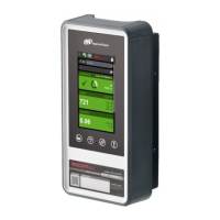
Ingersoll Rand 302 Series VFD Electrical
Installation
The voltage of the Ingersoll Rand 302 Series VFD is
dangerous when the unit is connected to the AC line.
Incorrect installation of the motor or Ingersoll Rand 302
Ingersoll Rand 302 Series VFD may lead to material
damage or serious injury or death. Follow the instructions
in this manual and comply to National Electrical Codes
(NEC) and local codes and safety guidelines.
DO NOT touch the electrical components of the
Ingersoll Rand 302 Series VFD for at least 15 minutes
after the AC line has been disconnected.
To avoid potential shock hazard when servicing a motor
or variable frequency drives, remove all power to all
drives having wiring that shares any conduit to be worked
on. If that is not possible, remove power to the drive and
ground the motor wires at the drive. When the work has
been completed, remove the grounds before reapplying
power to the drive.
In general, a conduit should not contain unshielded
power conductors for more than three PWM operated
motors.
It is the responsibility of the user or installer to
ensure correct grounding, branch circuit and motor
protection in accordance with the NEC and local codes
Connection of AC Line
Connect the three AC line phases to L1 (91), L2 (92), and
L3 (93) of the terminal block labeled Mains.
See Power Wiring Diagrams in the VSD
Interconnect Guide
To minimize electrical noise, install the drive within
100 feet (30 meters) of compressor.
To avoid electrical noise, do not route high-voltage
motor wires and low-voltage control wires through the
same conduit.
For proper safety, wire compressor and drive to a
common ground.
Schematics
The following table lists the electrical schematics that
illustrate the proper way to wire the Ingersoll Rand 302
Series VFD to the compressor. Locate the correct
schematic for the corresponding compressor and refer to
the Wiring Schematics section in this manual. The three
control relays, pressure transducer, and contactor (Sierra
only) should be wired per the proper schematic.
See Compressor Schematics in the VSD
Interconnect Guide
Safety Grounding
Please note that the Ingersoll Rand 302 Series VFD has
a high leakage current and must be grounded
appropriately for safety reasons. Use the ground
terminals (refer to the terminal drawings) which enable
reinforced grounding.
All national and local safety codes must be
observed.
See Power Wiring Diagrams in the VSD
Interconnect Guide
Motor Connection
The power cables from the Ingersoll Rand 302 Series
VFD connect to the motor terminal block located at the
bottom of the compressor’s starter box. The compressor
and fan motors’ leads are connected to the other side of
this block.
The power cables from the compressor/Ingersoll Rand
302 Series VFD system’s main disconnect (DIS1) to the
top of the compressor’s starter contactors should be
sized for the full amp rating of the machine. This setup
allows for the compressor to be quickly converted from
variable speed to constant speed control should the
Ingersoll Rand 302 Series VFD need servicing.
See Power Wiring Diagrams in the VSD
Interconnect Guide

 Loading...


