BNC Video Connector
*included with “HY”and “BNC” series only
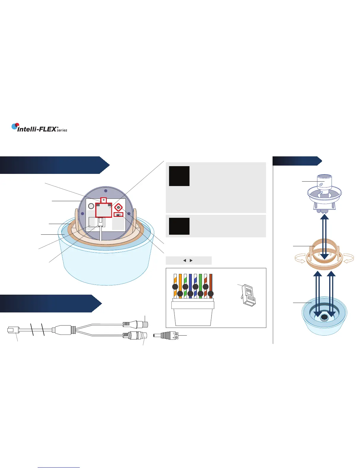
GIMBAL SYSTEM
Camera
Gimbal
Rotation
Base
Dome
Base
EXCA234 Series
INNOTECH TECHNICAL SUPPORT 954.792.2818 option #3
RJ45 Connector
Power Jack 12/24 Volt
FIGURE 1:
CAMERA, CONTROLS & CONNECTIONS
FIGURE 2:
RJ45 BREAKOUT CABLE
Camera Gimbal
ALIGN AS SHOWN
Test Monitor
Connector
Rotation Base
Dome Base
RJ45 Jack
RJ45 Breakout
Cable
Voltage Version Label
OSD Joystick
BNC/CAT5 Switch
BNC CAT5
N/A FOR 12VDC
ONLY VERSION
CAT5 Connection
• Set BNC/CAT5 Switch to “CAT5”
• Use CAT5 cable with SmartControl
Decoder.
(See Cat5 wiring detail below)
BNC Connection
• Set BNC/CAT5 Switch to “BNC”
• Use RJ45 Breakout Cable with 12VDC or 24VAC
P/S (camera auto senses voltage)
Screw Terminal Power Plug
• Observe polarity for 12VDC
• No polarity for 24VAC
12VDC Only
Use RJ45 Breakout Cable with 12VDC
P/S & Screw Terminal Power Plug
CAT5
12V AC
24V AC
BNC
12V DC
BNC
ONLY !
CAT5 WIRING DETAIL
Clip is pointed
away from you.
T-568B
o
g
b br
O
B
G
BR
1 2 3 4 5 6 7 8
RJ-45
Plug
Pin 1
INSERT
REMOVE
INSERT
REMOVE
 Loading...