Innovative Electronics © 2009
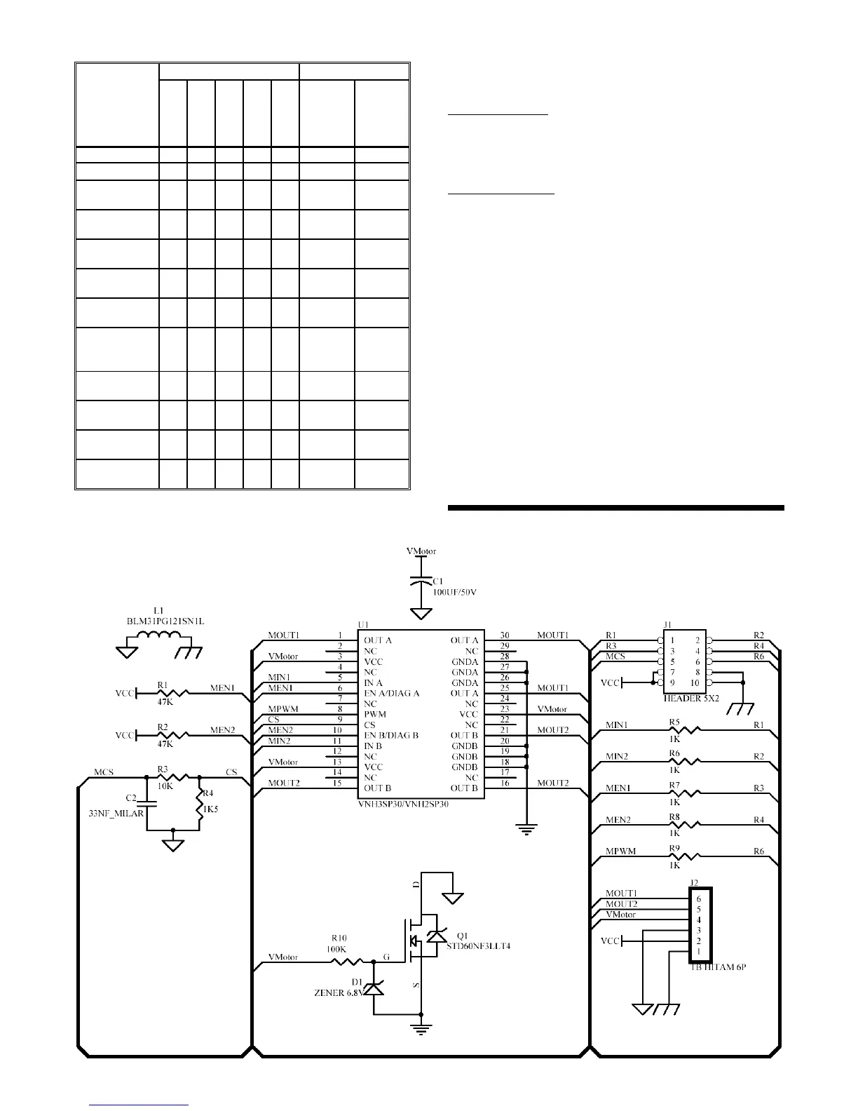
Truth table from the H-Bridge module is as follows:
H-Bridge
module
work status
Input and Status Output
MPWM
MIN1
MIN2
MEN1
MEN2
MOUT1
MOUT2
Forward H H L H H V MOT MGND
Reverse H L H H H MGND V MOT
Brake to
GND
H L L H H MGND MGND
Brake to
VCC
X H H H H V MOT V MOT
Free Running
Stop
L L L H H OPEN OPEN
Free Running
Stop
L H L H H V MOT OPEN
Free Running
Stop
L L H H H OPEN V MOT
Fault on
OUT1 and
OUT2
X X X L L OPEN OPEN
Fault on
OUT1
H X H L H OPEN V MOT
Fault on
OUT1
H X L L H OPEN MGND
Fault on
OUT2
H H X H L V MOT OPEN
Fault on
OUT2
H L X H L MGND OPEN
Description:
H = High L = Low
X = don’t care Z = High Impedance (Tri-state)
CD/DVD Content
1. EMS 30 A H-Bridge Manual & Quick Start.
2. Datasheet.
3. Innovative Electronics Website.
Testing Procedure
- Connect the power supply source for input (VCC) and
the power supply for load (V Mot).
- Perform testing by giving a High logic (+5V) or Low
(0V) to the input (MIN1, MIN2, MEN1, MEN2, and
MPWM) that matches the truth table.
- Output terminals (MOUT1 and MOUT2) will produce
output voltage that matches the functions stated in the
truth table.
♦ Thank you for your confidence in using our products, if
there are difficulties, questions, or suggestions
regarding this product please contact our technical
support :
support@innovativeelectronics.com
 Loading...