13
CPS 220/48.1/SV Montage- und Betriebsanleitung
CPS 220/48.1/SV Mounting and Operating Instructions
4.2. CPUSB 220 / 48.1 / 6
CPUSB 220 / 48.1 / 16
CPUSB 220 / 48.1 / 32
CPUSB 220 / 48.1 / 48
Die BUS-Unterstationen CPUSB 220 / 48.1 / ... ermögli-
chen, externe Stromkreise an die Zentralbatteriesysteme
CPS 220 / 48.1 anzuschließen. Über die 2-adrige Bat-
terieleitung werden die BUS-Unterstationen auch bei
Netzausfall mit Spannung versorgt. Die Überwachung
und Programmierung erfolgt über das Steuerteil des Zen-
tralbatteriesystems mittels der dreiadrigen Busleitung. Bei
Ausfall der BUS-Kommunikation schalten die Stromkreis-
module in den sicheren Betriebszustand.
Um die projektspezischen Anforderungen optimal
zu unterstützen, sind die BUS-Unterstationen eben-
falls in unterschiedlichen Ausbaustufen erhältlich:
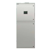
CPUSB 220 / 48.1 / 6
Auf einem Modulträger können bis zu 3 Stromkreismodu-
le (2x3A) eingesetzt werden.
Adressbereich über Adressschalter einstellbar
siehe 6.3.3.5. Adressierung - Seite 28
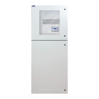
CPUSB 220 / 48.1 / 16
In einem 19“ Modulträger können bis zu 8 Stromkreismo-
dule mit unterschiedlicher Leistung (1x6A, 2x3A) einge-
setzt werden.
Adressbereich Modulträger: 1 bis 8, 9 bis 16, 17 bis 24, je
nach Ausführung
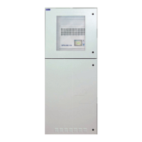
CPUSB 220 / 48.1 / 32
In zwei 19“ Modulträgern können bis zu 16 Stromkreis-
module mit unterschiedlicher Leistung (1x6A, 2x3A)
eingesetzt werden.
Adressbereich Modulträger 1: 1 bis 8
Adressbereich Modulträger 2: 9 bis 16
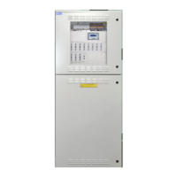
CPUSB 220 / 48.1 / 48
In drei 19“ Modulträgern können bis zu 24 Stromkreismo-
dule mit unterschiedlicher Leistung (1x6A, 2x3A) einge-
setzt werden.
Adressbereich Modulträger 1: 1 bis 8
Adressbereich Modulträger 2: 9 bis 16
Adressbereich Modulträger 3: 17 bis 24
Es ist darauf zu achten, dass jede Adresse je BUS
nur einmal verwendet werden darf!
4.2. CPUSB 220 / 48.1 / 6
CPUSB 220 / 48.1 / 16
CPUSB 220 / 48.1 / 32
CPUSB 220 / 48.1 / 48
The BUS sub stations CPUSB 220/48.1/… enable external
circuits to be connected to the central battery systems
CPS 220/48. The BUS sub stations are supplied with power
via the 2-wire supply lead, even if the power fails. Monito-
ring and programming is carried out via the central batte-
ry system controller by means of the three-wire BUS data
line. If the BUS communication fails, the circuit modules
switch to safe mode.
In order to support project-specic requirements opti-
mally, the BUS sub stations are also available invari-
ous expansion levels:
CPUSB 220 / 48.1 / 6
Up to 3 circuit modules (2x3A) can be used on a module
rack.
Address range congurable via address switches
see 6.3.3.5. Addressing on page 28
CPUSB 220 / 48.1 / 16
In a 19” module rack, up to 8 circuit modules with
various power values (1x6A, 2x3A) can be used.
Module rack address range: 1 to 8, 9 to 16, 17 to 24, de-
pending on design
CPUSB 220 / 48.1 / 32
In a 19” module rack, up to 16 circuit modules with
various power values (1x6A, 2x3A) can be used.
Module rack 1 address range: 1 to 8
Module rack 2 address range: 9 to 16
CPUSB 220 / 48.1 / 48
In a 19” module rack, up to 24 circuit modules with
various power values (1x6A, 2x3A) can be used.
Module rack 1 address range: 1 to 8
Module rack 2 address range: 9 to 16
Module rack 3 address range: 17 to 24
It is important to note that each address at every
bus may only be used once!
 Loading...