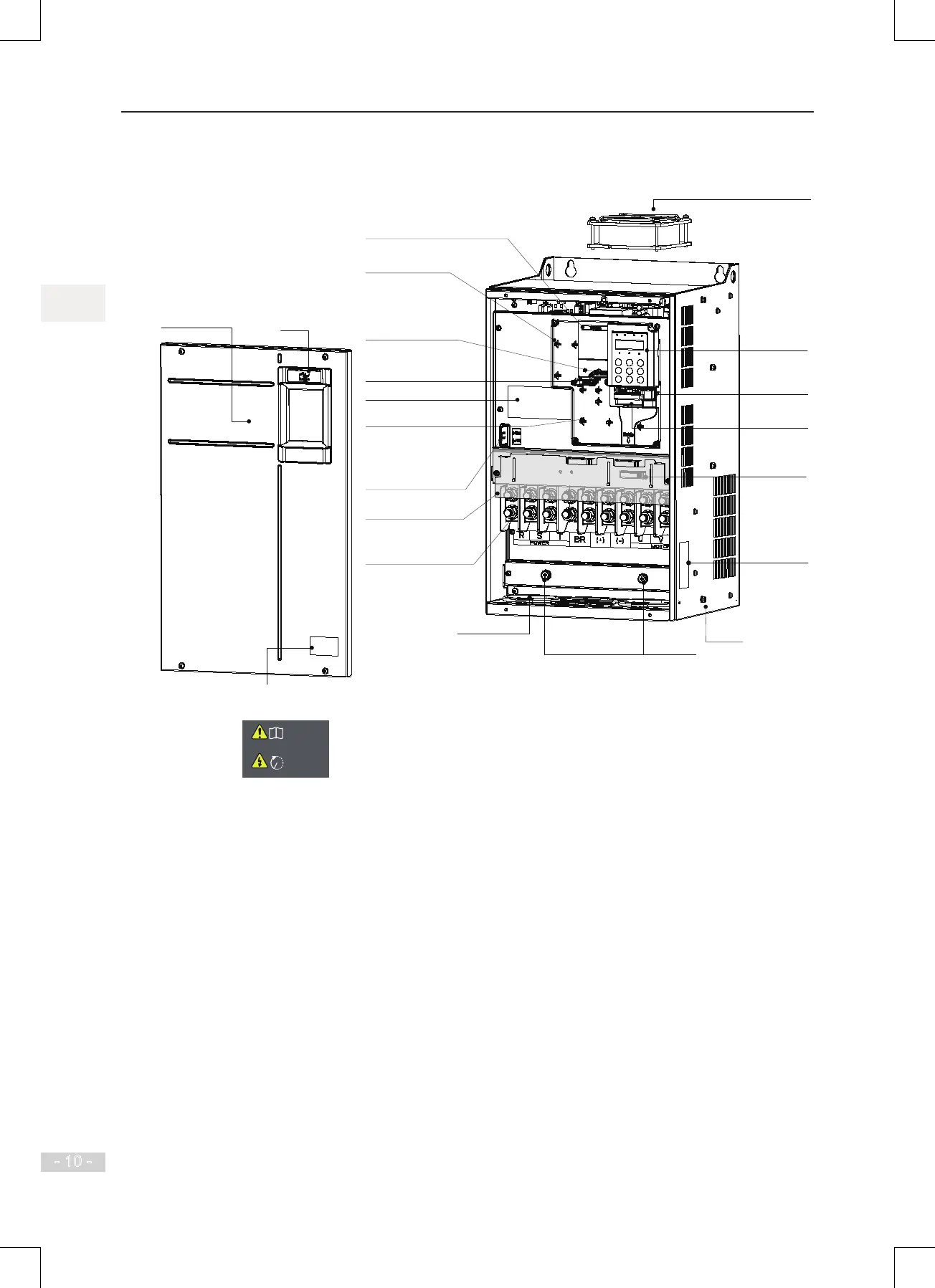
Logo
Grounding
terminal
See section 3.2.2.
Cable gland hole
Housing
Warning label
Wiring description label
Protective cover of
main circuit terminals
Front cover
For removal of the front
cover, see section 2.5.
Barcode
View the serial number and model of the drive here.
Fixing pin of
extension PG card
See section 8.4.3.
Cabling tray and
fixing pin of ground
cable of control board
This ground cable can only be
connected to the ground bar after the
system is grounded reliably.
Otherwise, connect it to the fixture.
Main circuit terminals
See section 3.2
.1.
EMC and VDR screw
Refer to Power Grid System in
section 3.2.2 and requirement on
current leakage in section 9.
1.8.
Fixing pin of extension card
See sections
8.4.1 and 8.4.2.
Grounding bar
Ground the PG card and control
board only after ensuring reliable
system grounding.
Cooling fan
For replacement, see section
10.
3
.
Nameplate
Refer to Figure 1.1.
Operating panel
See section 4.2.
Interface of
external
operating panel
Refer to section 8.3.
Control Circuit
Terminals
See section 3.3.1.
Cable tie
Fix signal cables
Read the user manual of the MD500 AC drive carefully before installation or operation.
Do not remove the front cover while the power is on or within10
minutes after the power is turned off.
Wait for a period of 10 minutes after the AC drive is powered off
before starting any repair, maintenance or wiring work .
i
10min

 Loading...