Intel Desktop Board DZ77SL-50K Technical Product Specification
46
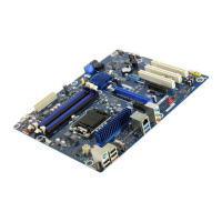
Table 12 lists the component-side connectors and headers
identified in Figure 10.
Table 12. Component-side Connectors and Headers Shown in Figure 10
Item/callout f
rom Figure 10
Des
cription
A Conventional PCI add-in card connector
B Conventional PCI add-in card connector
C Conventional PCI add-in card connector
D Front panel USB 3.0 connector (blue)
E PCI Express x4 add-in card connector
F Rear chassis fan header
G PCI Express x16 add-in card connector
H PCI Express x1 add-in card connector
I 12 v processor core voltage connector (2 x 4 pin)
J Processor fan header
K Front chassis fan header
L Consumer IR receiver (input) header
M Consumer IR emitter (output) header
N Main power connector (2 x 12)
O SATA 6.0 Gb/s connector through the PCH (blue)
P SATA 3.0 Gb/s connector through the PCH (black)
Q SATA 3.0 Gb/s connector through the PCH (black)
R Chassis intrusion header
S Alternate front panel power/sleep LED header
T Front panel header
U LPC Debug header
V Front panel USB 2.0 header
W Front panel USB 2.0 header
X S/PDIF out header
Y Front panel audio header