Hot Swap Drive Cage Upgrade Install Instructions (optional)
Intel® Entry Server Chassis SC5299-E UP/DP/WS/BRP User Guide 69
17. Make backplane and server board/RAID controller card cable connections. Cable
instructions will differ depending upon whether you are installing a SCSI or SAS/
SATA hot swap drive cage. Refer to the documentation that came with your server
board and/or RAID controller card for instructions on connecting backplane cables to
your server board or RAID controller card.
Warning: It is critical that you connect the SAS/SATA data cables correctly from the
SAS/SATA backplane to your server board or RAID controller card.
Failure to do so may result in data loss.
Note: Connect the SES cable from the backplane to the RAID card (if one is
installed).
a.
If you are installing a six-drive SCSI hot swap drive cage:
i. Connect the two power cables (see letter “A” in the following figure) to the two
power cable connectors on the SCSI backplane.
ii. Connect the SCSI data cable (see letter “B”) to the SCSI connector on the SCSI
backplane.
iii. (Optional, dependent on server board installed) Connect the IPMB header (see
letter “C”) to the IPMB connector on the SCSI backplane.
iv. Connect the fan power to the server board. For the Intel® Server Board
S5000VSA, use FAN1. For other Intel® server boards, refer to the Quick Start
User’s Guide that came with the server board.
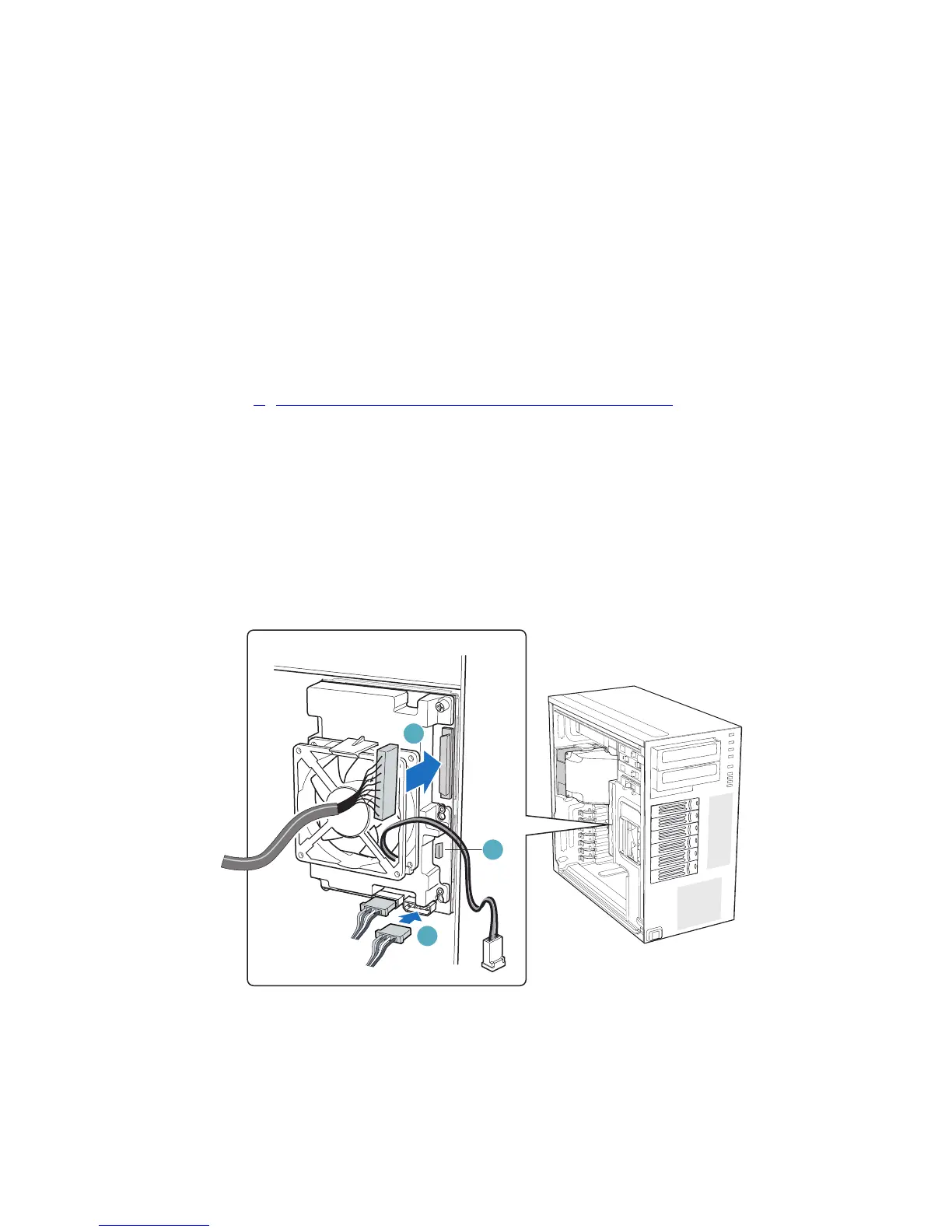
Figure 86. Cabling the SCSI Hot Swap Drive Cage (DP/WS/BRP configuration shown)
TP02056
A
B
C
 Loading...


