Do you have a question about the Inter-m PAM-120A and is the answer not in the manual?
Specifies the ideal operating environment for the product, avoiding heat, dust, moisture, and vibration.
Crucial safety guidelines for installation and operation, including water proximity and ventilation.
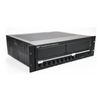
Allows installation of optional modules like CD player or tuner for expanded audio capabilities.
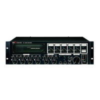
Rear-panel controls for managing individual input channel levels.
Switches enable selection of up to five individual speakers.
Assigns audio priority to specific inputs like Channels 1 and 2 over others.
Enables wired remote control for speaker zone selection and chime activation.
Provides a convenient four-tone chime for use with announcements.
Optional feature for EM broadcasting stored in VOICE IC during emergencies.
Slot for installation of the optional PAM-T (AM/FM Tuner) Module.
Slots for installing optional PAM-CDA (CD Player) or PAM-D (Cassette Deck) Modules.
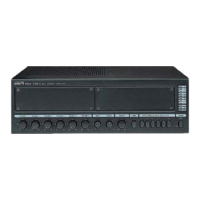
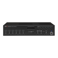
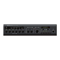
Seven-segment LED meter indicating the amplifier's output level in RMS.
Controls individual volume levels for Channels 1 through 6.
Individual Bass and Treble controls for adjusting frequencies.
Rotary switch controlling the overall output volume of the amplifier.
Activates the amplifier's chime circuitry.
Switches used to select output to any combination of up to five individual speakers.
Turns the unit on or off, indicated by the Power LED.
LED indicating the status of the amplifier's protection circuitry.
Connects up to five individual speakers to the terminal strip.
Selects between 70V or 100V distributed systems for high impedance operation.
Terminal for connecting the antenna for the optional PAM-T AM/FM Tuner module.
Three-band equalization controls for adjusting high, mid, and low frequencies.
Supplies +22V DC to microphone inputs for condenser microphones.
Grants priority to Channels 1 and/or 2 over all other channels and audio inputs.
Connection point for the standard three-pin AC power cable.
Activates the four-tone chime circuitry when terminals are shorted.
Mutes signals from channels 3-6 and optional modules via wired remote.
Terminals for connecting a 24VDC battery source for backup power.
Output for connecting the unit to an external power amplifier.
Input for an external mixer or preamp to the unit's power amp.
Line-level input for connecting the unit with an external mixer.
Balanced XLR connectors for microphone or low impedance signals.
Knobs providing continuous control of input levels for each of the six input channels.
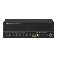
Connects up to five individual speakers to the terminal strip.
Terminal for connecting the antenna for the optional PAM-T AM/FM Tuner module.
Three-band equalization controls for adjusting high, mid, and low frequencies.
Supplies +22V DC to microphone inputs for condenser microphones.
Grants priority to Channels 1 and/or 2 over all other channels and audio inputs.
Connection point for the standard three-pin AC power cable.
Handles emergency broadcasting when the EM switch is pressed.
Activates the four-tone chime circuitry when terminals are shorted.
Mutes signals from channels 3-6 and optional modules via wired remote.
15-pin D-SUB for wired remote control of speaker zones and chime.
Output for connecting the unit to an external power amplifier.
Input for an external mixer or preamp to the unit's power amp.
Line-level input for connecting the unit with an external mixer.
Balanced XLR connectors for microphone or low impedance signals.
Knobs providing continuous control of input levels for each of the six input channels.
Guidance on connecting conventional low-impedance speakers.
Instructions for connecting high-impedance speakers in parallel.
Schematic representation of the PAM-120A's internal circuitry.
Schematic representation of the PAM-340A/480A's internal circuitry.
Steps to ensure problems are not due to operator error before contacting support.
Information on how to obtain the unit's schematic diagram.
Information on how to obtain the unit's parts list.
Notes on product compatibility with local AC power requirements.
Indicates that no optional items are available for this product.
| Power Output | 120W |
|---|---|
| Frequency Response | 20Hz - 20kHz |
| Total Harmonic Distortion | 0.1% |
| Output Impedance | 4Ω |
| Inputs | XLR |
| THD (at 1kHz) | <0.1% |
| Power Source | AC 220-240V, 50/60Hz |
| Input Impedance | 20kΩ (Balanced), 10kΩ (Unbalanced) |