TruPortal Dual Door Interface Quick Reference 2 P/N 460802991B 26JAN12 en-US
Reader Wiring
For the second reader of each door, the reader connections are shared
(except for the Data 0 and Data 1 which are separate for each reader).
Jumpers
Reader power for Door 1 [J1] and Door 2 [J2]:
• 5V = 12V reduced to 5V at door
• 12V = 12V passed through to reader
Status LEDs
• LED 1: This is the Processor OK LED. Its normal action is a slow
flash.
• LED 2: This is the SNAPP OK LED. If the module serial number is
configured and communicating with the main panel then the LED is
on. If the module serial number is not programmed or not
communicating the LED is off.
• LED 3: This is the Power BAD LED. If there is insufficient voltage or
current then this LED will flash. If the voltage is normal then the LED
is off.
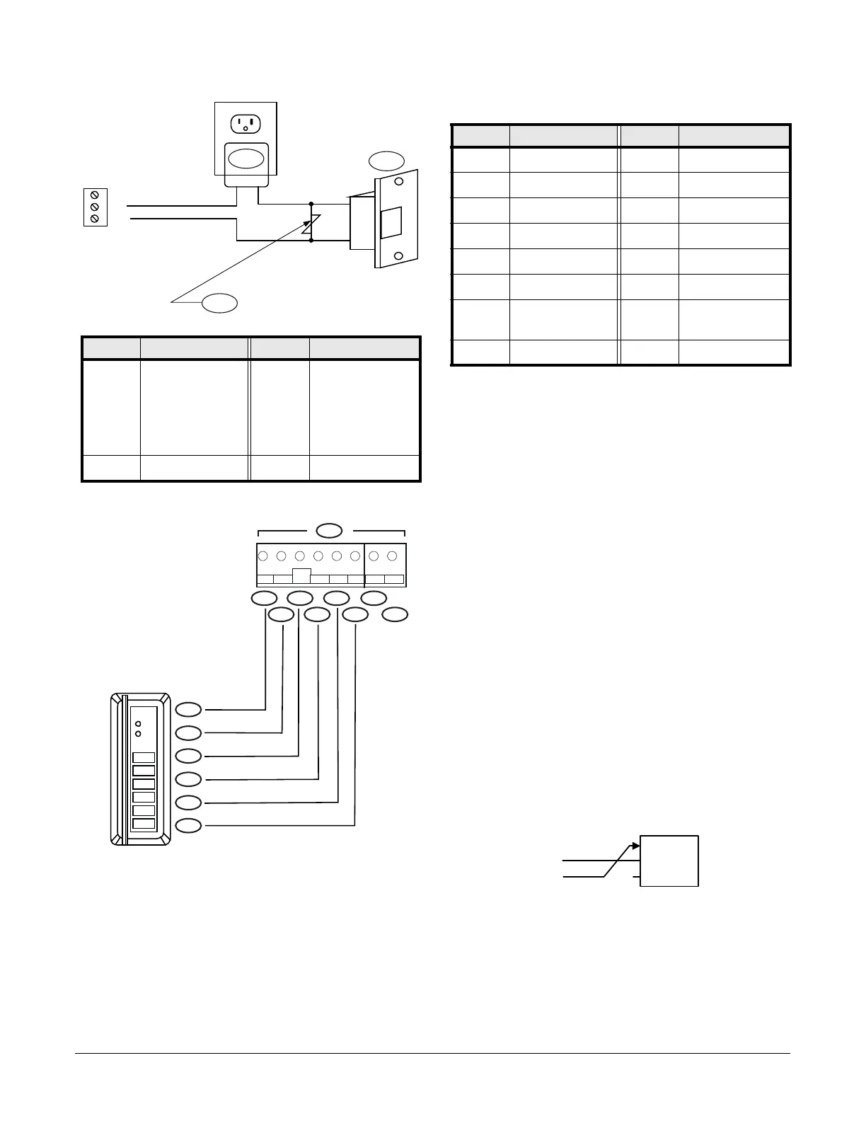
Magnetic Locks and other “Fail-Safe” Door Locks
The default door lock wiring is for “Fail Secure” (powered = unlocked). For
magnetic-locks and other “Fail-Safe” door locks (powered = locked), move
the NO wire to NC terminal for the specific unlock relay.
Note: The system shall not be installed in the fail secure mode unless
permitted by the local authority having jurisdiction and shall not
interfere with the operation of panic hardware. (Not evaluated by
UL.)
Callout Description Callout Description
1 AC transformer 3 Clamp voltage
>1.5x VAC RMS.
For 24 VAC strike,
Panasonic
ERZ-CO7DK470 is
typical.
2 AC strike
123456 12
TB11
5/12 GRN
RED/
RXD GNDR1D1 R1D0 R2D1 R2D0
01
23
45
67
89
*
#
5
4
1
3
2
10
9
6 8
7
15
14
13
12
11
Callout Description Callout Description
1 Reader 9 R2 Data 0
2 (+) 5/12 VDC 10 Red (1)
3 Green LED 11 Brown (4)
4 Red LED 12 Orange (5)
5 R1 Data 1 13 White (3)
6 R1 Data 0 14 Green (2)
7 (-) 0V Signal
Ground
15 Black (6)
8 R2 Data 1
 Loading...