Component Overview
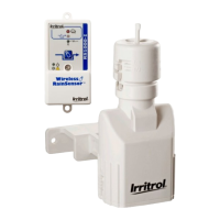
Receiver (Figure 1)
1- Weather-resistant Cover:
Slides upward to remove. Protects
the receiver module when located
outdoors. Keep the cover installed
at all times other than when
manually operating the receiver.
2- Antenna wire:
Straighten vertically for the best
reception.
3- Sensor Status Indicator:
Steady light - Sensor is active
(either rain or freeze).
Blinking light - Indicates receiver
has been bypassed for one rain
cycle. Smart Bypass
TM
button
pressed once. Press again to exit
bypass mode.
4- Signal Indicator: Indicates quality of last received signal.
Steady light - good signal.
Blinking light - fair signal.
No light - poor signal (relocate Sensor Transmitter).
5- Smart Bypass
TM
Button:
Press to temporarily override the sensor when active.
Press and hold for 5–7 seconds to turn off the receiver.
6- Power Indicator:
Steady light - 24 VAC power is connected.
Blinking light - Sensor/Transmitter battery power low, or other communication
problem.
No light - Unit is off or is disconnected from 24 VAC.
7- Multi-wire Cable: 20" (50cm) color-coded wires provided for controller connections.
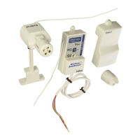
Sensor/Transmitter (Figure 2)
1- Spindle: Press down and hold to
manually test transmitter operation.
2- Rainfall Adjustment Cap: Adjusts the
Sensor/Transmitter to signal the
receiver when the accumulated rainfall
reaches 1/8" (3mm), 1/4" (6mm), 1/2"
(12mm) or 3/4" (19mm).
3- Vent Ring: Adjust “dry-out” rate.
4- Universal Mounting Bracket with
Quick-Clip
TM
: Simplifies installation on
rain gutter, or roof eaves, fences, etc.
Sensor/Transmitter adjusts easily to
the vertical position.
5- Conduit Adapter:Alternative
mounting option for conduit mount.
6- Antenna Wire: Straighten downward
for maximum range.
2
1
3
4
5
6
7
2
1
2
3
4
Figure 1
Figure 2
6
5
 Loading...