Quick Start Installation Instructions
The following instructions are provided for the experienced installer.
Refer to Figures 3–5 below.
Note: When installing Sensor/Transmitter model RFS1000-I for freeze detection, refer
to additional freeze sensor installation information on page 8.
1. Disconnect power to the irrigation system controller.
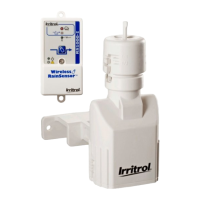
2. Always mount the Receiver FIRST, adjacent to the controller with either the provided
stainless steel screws or double-sided foam tape.
3. Attach Receiver control wires to the sensor inputs OR to break the valve common:
a. Disconnect valve common wire and pump/master valve common wire (if present).
b. Attach White wire to common wire(s) with a wire connector.
c. Attach Brown wire to valve common terminal (the Yellow wire not used in this
application).
4. Connect the Red wires to the controller’s 24 V ac power source terminals.
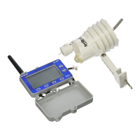
5. Straighten the Receiver antenna wire upward and the Sensor/Transmitter antenna
wire downward.
6. While holding the Sensor/Transmitter at close range to the Receiver, press and hold
the test spindle to test the wiring. The Power , Signal and Sensor Status
indicators should be ON.
7. Adjust the Rainfall Adjustment Cap to the desired rainfall activation amount.
8. Mount the Sensor/Transmitter in an unobstructed location away from sprinklers.
9. Important: Reconfirm proper operation of the Sensor/Transmitter at the final
mounting location.
3
Red
To 24 V ac
To 24 V ac
To Sensor Terminal or to Break Valve Common
To Sensor Terminal (Normally Closed)
or to Break Valve Common
To Sensor Terminal (Normally Open)
(For Normally Open sensor, see Detailed Instructions)
Red
White
Brown
Yellow
Figure 3
Antenna wire
extended
straight down
Rain gutter (cross section view)
Do not over-tighten
thumbscrew
Press and hold
down to test
Figure 4
Antenna wire extended
straight down
Stainless
Steel
Screws
Figure 5
Wireless RS 373-0312 redo 1/27/04 8:55 AM Page 3
 Loading...