Rainfall Adjustment
Prior to installing the Sensor/Transmitter, check the current
setting of the Rainfall Adjustment Cap. The RainSensor can
be adjusted to detect an average rainfall amount of 3 mm,
6 mm, 13 mm, 19 mm or 26 mm before suspending watering.
To adjust, turn the cap from the current setting and engage
the stationary pins with the desired slot position. Be sure to
align the slot and pin properly as this adjustment does not
require excessive force. See Figure 10
Note: Avoid using the 3 mm setting in high-humidity conditions.
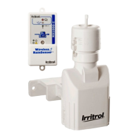
Installing the Sensor/Transmitter
Note: If installing Wireless RainSensor model RFS1000-I for freeze detection, please
refer to additional instructions provided on page 8.
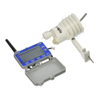
Testing Signal Strength at the Installation Site
The Receiver’s Signal Indicator provides an indication of the strength of the last
valid received signal. Prior to testing the Sensor/Transmitter in its final location, clear
the Signal Indicator first so the test will represent the signal as received during the
final check. To clear the Signal Indicator from previous tests, simply press the Smart
Bypass button once, then once again to exit the bypass mode. Prior to final place-
ment, test the Sensor/Transmitter signal by lightly pressing and holding the test spin-
dle as described in “Initial Signal Testing” on page 6.
Note: If the location of the Sensor/Transmitter is not providing a valid signal to the
Receiver, verify Sensor/Transmitter operation at
close range and choose another mounting location.
For additional information, refer to “Solving
Reception Problems” on page 10.
Tip! If the Receiver is not visible to the installer,
turn on a watering zone which is visible from the
installation location and the activation of the
Sensor/Transmitter will shut off the “test” zone.
Please note that the manual activation cycle of
some controllers bypasses the sensor inputs.
You will need to run an automatic/timed watering
program for these types of controllers.
Installation
The Sensor/Transmitter should be mounted verti-
cally with the antenna wire extending straight
down. Avoid installations where the antenna
wire would contact any metal object.
Mount the Sensor/Transmitter as close to the
Receiver as possible to avoid interference of the
wireless signal. The unit should be exposed to
unobstructed rainfall, but not in contact with sprin-
kler spray or runoff from the roof.
Mounting to the outside edge of a rain gutter is sim-
ple with the Quick-Clip
TM
bracket. See Figure 11.
The Sensor/Transmitter can also be mounted on
any suitable solid structure using the supplied
stainless steel screws. See Figure 12.
7
Figure 10
6 mm
13 mm
26 mm
19 mm
3 mm
Antenna wire
extended
straight down
Rain gutter (cross section view)
Do not over-tighten
thumbscrew
Figure 11
Antenna wire extended
straight down
Stainless
Steel
Screws
Figure 12
Wireless RS 373-0312 redo 1/27/04 1:56 PM Page 7
 Loading...