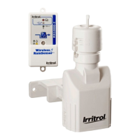
Receiver Learn Mode
If it becomes necessary to set the Receiver’s address code to that of a new
Sensor/Transmitter, press and hold the Smart Bypass button until the Sensor Status
Indicator and Signal Indicator blink in unison (10+ seconds). Activate the corre-
sponding Sensor/Transmitter at close range (by pressing down on the test spindle) to
change the existing Receiver code to that of the new Sensor/Transmitter. The indicators
will stop blinking upon learning the new code. Pressing the Smart Bypass button again
will exit the learn mode if no valid code is received.
Attention Required
When the Power Indicator blinks, it indicates that either of the following conditions
exists:
• The Sensor/Transmitter’s battery is getting low and should be replaced when convenient.
The Wireless RainSensor will function properly for some time after this indicator is
present.
• If the batteries are good, a problem with communication is indicated. Relocating the
Sensor/Transmitter may be necessary to provide a better signal.
Sensor/Transmitter Battery Replacement
1. Remove the bottom cover of the
Sensor/Transmitter by gently pressing in and
down on the lower opposing tabs using a small
flat-blade screwdriver, then carefully slide the
circuit board out. See Figure 13.
2. Without tools, remove the battery cover and
replace using two 3V CR2032 (or equivalent)
batteries. Install with positive (+) side of the
batteries facing up.
Note: Properly dispose of used batteries per
battery manufacturer’s recommendations.
3. Reassemble the unit in reverse order.
Changing the Sensor/Transmitter Code
The transmission code for the Wireless
RainSensor is identified by stickers on the
Sensor/Transmitter and Receiver. Although, in
most cases, even if two identical units are
installed, unwanted activations would only occur if
the two Sensor/Transmitters were set for different
rainfall amounts. However, the code may be man-
ually changed as follows:
1. Remove the bottom cover of the
Sensor/Transmitter by gently pressing in and
down on the the lower opposing tabs using a
small flat-blade screwdriver, then carefully slide
the circuit board out. See Figure 13.
2. Identify the code wire loops (small black wire and white wire loops) and cut one or
both loops using end-cutting pliers.
3. Reassemble the Sensor/Transmitter and follow the procedures provided in “Receiver
Learn Mode” above.
9
Battery
Cover
CR2032
Batteries
Transmitter
Code Wire
Loops
Figure 13
Wireless RS 373-0312 redo 1/27/04 8:55 AM Page 9

 Loading...