Installation & User Guide
Connection
The RD810 receiver requires continuous 12 Volt DC power, normally from a regulated power supply but a
battery or solar supply may be used if it meets the power requirement specification. The power source must be
free of voltage surges and spikes, and capable of continuously supplying receiver current.
Connect the RD810 receiver to the power and external control circuits with the #18 lead wires extending
from the receiver base. Follow the wire color codes as shown in the diagram on page 3. The wires may be spliced
as necessary to reach the power supply and the external circuits, but always ensure that the wire size is adequate
to maintain 12 volts DC at the full rated load of the receiver, plus any external devices connected to the power
supply. Use care in wire splicing, as poorly made wire splices are a common source of operational problems.
See the listing of Isaacs power supplies and receiver accessories that are available on page 4.
Operation and Maintenance
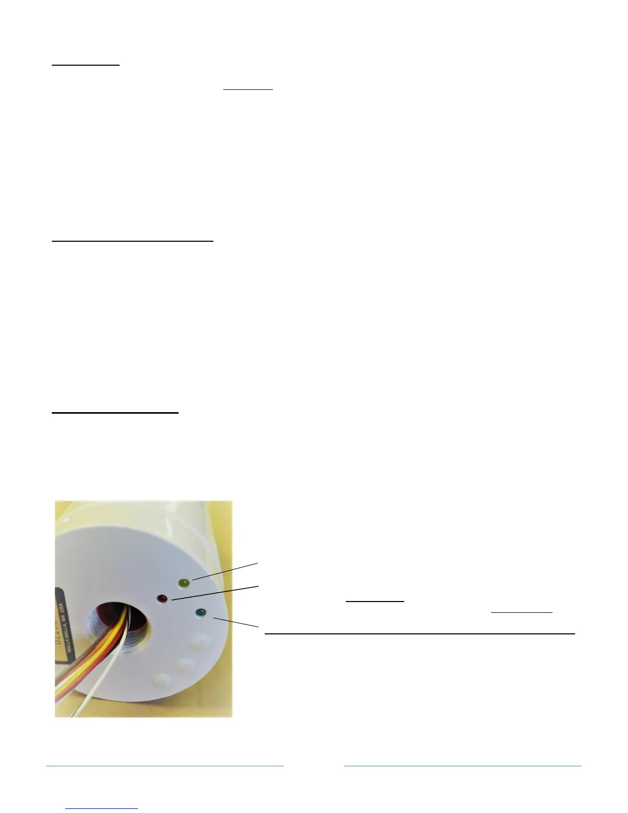
As shown in the photo below, the three LEDs in the receiver base indicate receiver power (red illuminated),
a fault (yellow illuminated), and/or the output relay is energized (green illuminated). During initial power-up, the
receiver will self-test and may briefly illuminate all the LEDs, but only the red LED should remain “on” which
indicates the receiver is powered. There will be no further LED activity until the receiver detects a signal from the
valid transmitter with its contacts in an active state (green LED), or until a fault is detected (yellow LED).
A fault condition at the receiver indicates either a transmitter problem such as low battery voltage, or that
the receiver has lost communication with a transmitter for an extended interval (typically set for 2 hours).
The RD810 receiver requires no routine maintenance. Refer to the Isaacs Wireless Troubleshooting Guide
if operational problems occur.
System programming
The term “system” refers to the wireless units mated by programming. Only those units that interact
because of their unique programming comprise a particular system. Multiple systems may operate in a given area
without interference. The components and operation of this specific system are as follows:
Receiver Ser. No.___________
Additional programming information (see pg. 4): YES___ NO___
FAULT (Yellow)
POWER (Red)
TRANSMITTER LED “ON” WHEN
Model Ser. No. TX contacts are:
OUTPUT .
 Loading...