ARMY TM 9-2815-254-24
AIR FORCE TO 38G1-94-2
b.
Install PCV assembly, refer to paragraph 3-20.3.
c.
Install valve rocker oil feed pipe, refer to paragraph 3-16.2.
d.
Perform adjustment procedures, refer to paragraph 3-26.6.
e.
Position new preformed packing (6) and rocker cover (5) on cylinder head and secure with two bolts (1), wash-
ers (2) and new gaskets (3). Tighten bolts to 114 in-lbs (13.0 Nm)
3-26.6. Adjustment.
a.
Remove rocker cover (5, FIGURE 3-52) if not already removed, refer to paragraph 3-26.1.
b.
Ensure all eight retaining plate bolts (7) are tight. If not, tighten in accordance with paragraph 3-26.5.
c.
Rotate crankshaft until crankshaft pulley TDC line is aligned with timing pointer. This will bring piston in No.
1 or No. 4 cylinder to TDC on compression stroke.
d.
Check for play in No. 1 intake and exhaust valve push rods. If push rods have play, No. 1 piston is at TDC
on compression stroke. If push rods are depressed, No. 4 piston is at TDC on compression stroke.
e.
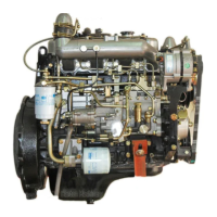
Adjust valve clearance for rocker arms shown in View A of FIGURE 3-59 as follows:
(1) Loosen nut (19, FIGURE 3-52) and adjusting screw (20).
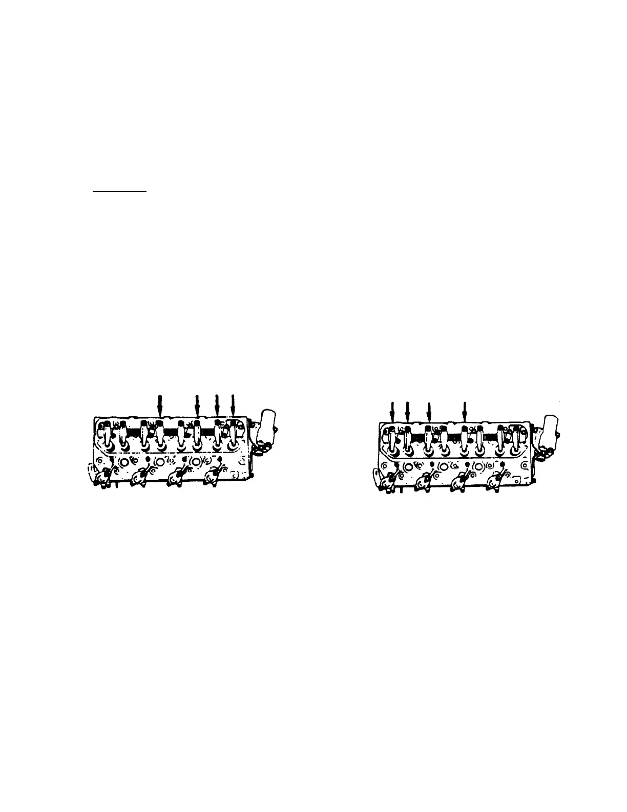
VIEW A
VIEW B
FIGURE 3-59. Valve Clearance Adjustment Sequence
3-109

 Loading...