EasyManua.ls Logo

Italsea 7CH4Q107 - User Manual

Italsea 7CH4Q107
22 pages
Print Icon
To Next Page IconTo Next Page
Loading...
7CH4Q107_E_4 DATE : 28/06/2013 REV. 4.0
7CH4Q107
MICROPROCESSOR FOUR QUADRANT CONTROLLER FOR
PM DC MOTORS EXTERNAL PROGRAMMER
- USER’S GUIDE -
Question and Answer IconNeed help?

Do you have a question about the Italsea 7CH4Q107 and is the answer not in the manual?

Summary

Introduction to the 7 CH4 Q107 Controller

Key Features Overview

Overview of the controller's key technical specifications and capabilities.

Mechanical Dimensions and Connections

Controller Installation Guide

Complete Wiring Diagram

I;O Connector Pin Definitions

Potentiometer Supply and Reference Inputs (Pins 1-3)

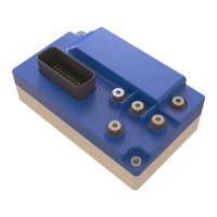
Pins for potentiometer voltage supply and speed reference input.

Max Speed Input and Safety Input (Pins 4-5)

Inputs for maximum speed potentiometer and backward safety contact.

Disable Input and Electrobraking Coil (-) (Pins 6-7)

Pins for disabling operation and the electrobrake coil negative connection.

Electrobraking;Horn Coil (+) and Horn (-) (Pins 8-9)

Common positive supply for electrobrake/horn and horn negative output.

M5 Power Screw Connections

Handheld Programmer Operation

Programmer Interface and Basic Navigation

Overview of the programmer's LCD display, buttons (UP, MODE, DOWN), and basic navigation.

Tester Mode Functionality

Explanation of the initial 'Tester Mode' display showing motor current, voltage, and other parameters.

Entering Programming Mode

Steps to enter the programming mode, select, change, and confirm parameters.

Handheld Programmer Tester Mode Details

Controller Alarms and Troubleshooting

Alarm A1 & A2: Switch Issues

Troubleshooting for forward/backward switch status at power-on.

Alarm A3 & A4: Potentiometer Issues

Troubleshooting for potentiometer faults or incorrect neutral position.

Alarm A5 & A6: Thermal & Power Stage

Addressing thermal protection and power stage damage issues.

Alarm A7: Overcurrent;Short Circuit

Procedure for handling overcurrent and short circuit alarms.

Additional Controller Alarms

Alarm A8: Overcurrent;Short Circuit (2)

Handling second overcurrent or short circuit alarms.

Alarm A9 & A10: Voltage Issues

Troubleshooting undervoltage and overvoltage conditions.

Alarm A11: Overload Protection

Procedure for overload protection activation and resolution.

Alarm A12-A14: System & Configuration Faults

Addressing disable switch, key-off sequence, and EEPROM failure alarms.

Handheld Programmer Parameter Configuration

F0: Default Parameter Settings

Option to load factory default parameter values.

F5: Acceleration and Deceleration Ramps

Adjusts acceleration and deceleration ramp times for smooth operation.

F9 & F22: Speed Settings

Configures forward and backward maximum speed limits.

F17 & F18: Overload Protection Settings

Sets rated current and overload time for motor protection.

Controller Reset and General Settings

Reset to Default Parameters

Procedure to restore all controller parameters to factory defaults.

Acceleration Ramp (F5)

Sets the time for acceleration from stop to maximum speed.

Reverse Deceleration Ramp (F6)

Sets the deceleration time for reversing direction.

Neutral Deceleration Ramp (F7)

Sets the deceleration time to stop from maximum speed.

Speed and Voltage Parameter Settings

Forward and Backward Speed Configuration

Sets maximum speed percentages for forward and backward operation.

Minimum Speed Setting

Defines the minimum speed as a percentage of battery voltage.

Battery Voltage Selection

Configures the controller for 24V or 36V battery supply.

RxI Compensation Setting

Parameter for RxI compensation to improve performance.

Speed Reference Settings

Single-ended Potentiometer Calibration

Steps to calibrate a single-ended potentiometer for speed reference.

Wigwag1 Potentiometer Calibration

Steps to calibrate a Wigwag1 potentiometer with enable switches.

Wigwag2 Potentiometer Calibration

Steps to calibrate a Wigwag2 potentiometer without enable switches.

Single-Ended Potentiometer Calibration Steps

Step 1: Potentiometer Course Setup

Configure the potentiometer course range selection.

Step 2: Potentiometer Course Confirmation

Confirm the potentiometer course setting.

Step 3: Zero Point Calibration

Set and confirm the zero (neutral) voltage point for the potentiometer.

Step 4: Maximum Point Calibration

Set and confirm the maximum voltage point for the potentiometer.

Wigwags Potentiometer Calibration Steps

Speed Reference Type Configuration

Select and confirm the speed reference type (single-ended or wigwag).

Potentiometer Course Configuration

Configure and confirm the potentiometer course setting.

Voltage Range Calibration (Zero, -Vmax, +Vmax)

Calibrate the zero, negative maximum, and positive maximum voltage points.

Controller Output Settings

Reference Deadband Setting

Configures the deadband for the speed reference input signal.

Electrobraking Output Configuration

Details on the electrobrake coil operation and timing.

Multimode Input Configuration

Multimode Speed Setting (F24)

Sets a reduced speed based on the multimode input.

Multimode Current Setting (F25)

Sets a reduced current based on the multimode input.

Backward Safety Settings

Backward Safety Time (F21)

Sets the duration for the backward safety function.

Backward Safety Speed (F27)

Sets the speed limit for the backward safety function.

Overload Protection Configuration

Rated Current and Overload Time Settings

Configures the motor's rated current and overload time parameters.

Overload Protection Calculation

Formulas and examples for calculating overload protection parameters.

Engineering Protected Parameters

IGSL and PGSL Parameters

Settings for IGSL and PGSL, likely related to speed or current limits.

IGCL and PGCL Parameters

Settings for IGCL and PGCL, possibly for current or gain control.

LPOT and CPOT Parameters

Settings for LPOT and CPOT, potentially related to potentiometer inputs.

Overview

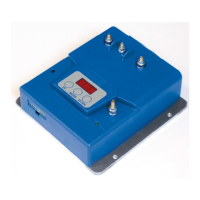
The Italsea 7CH4Q107 is a sophisticated four-quadrant chopper designed for controlling PMDC motors, particularly in traction applications powered by 24V or 36V batteries. At its core, the device utilizes a powerful microprocessor to provide digital control over motor speed and current regulation. This intelligent control system is further enhanced by an efficient diagnostic capability that identifies failures and incorrect wiring connections, ensuring reliable operation and simplifying troubleshooting. The programmability of its main parameters allows for flexible adaptation to various application requirements.

The power stage of the 7CH4Q107 is configured as an "H bridge" and operates using Pulse Width Modulation (PWM). This design choice results in a very low current ripple, which significantly contributes to the high efficiency of the system. The chopper is engineered to comply with major EC standards, underscoring its quality and safety.

Function Description

The primary function of the 7CH4Q107 is to precisely control the speed and current of PMDC motors. It achieves this through a four-quadrant operation, meaning it can provide power in both forward and reverse directions, as well as regenerative braking. This capability is crucial for applications requiring dynamic control, such as electric vehicles or material handling equipment.

The device integrates a comprehensive set of safety features to protect both the controller and the motor. These include output short circuit protection, MOSFET short circuit protection, and thermal protection to prevent overheating. It also incorporates low voltage and overvoltage protection to safeguard against battery irregularities, as well as reverse battery protection. An overcurrent protection function, which is temperature-dependent, further enhances the device's resilience. Additionally, it can detect faults in the potentiometer and associated wiring, ensuring accurate speed reference input.

Speed reference can be provided either through a voltage signal (0.5-4.5Vdc) or a 1-10 kΩ potentiometer, offering versatility in control input. An on-board main contactor, rated for 24V-80A continuous operation, manages the main power supply to the motor. Regenerative braking is a key feature, allowing energy to be recovered during deceleration, which can improve overall system efficiency and extend battery life.

Usage Features

The 7CH4Q107 is designed for ease of use and configuration, primarily through an external handheld programmer, the 7PROGLCD. This programmer serves as the main interface for displaying parameters, alarms, and measurements, as well as for configuring the controller's settings.

Upon power-on, the handheld programmer defaults to a "Tester Mode" page. In this mode, users can monitor critical operational data such as motor current and voltage, speed reference input, internal aluminum heatsink temperature, battery voltage, hour-meter readings, and the software release version. This real-time diagnostic information is invaluable for monitoring system health and performance.

To access the programming functions, the user presses the "MODE" button on the handheld programmer. This action brings up the first parameter. The "UP" and "DOWN" buttons are then used to navigate through the list of parameters. Once a desired parameter is selected, pressing "MODE" again enters the change menu, allowing the user to adjust its value using the "UP" and "DOWN" buttons. Confirming the new value is done by pressing "MODE" once more. To exit the programming menu and return to the "Tester Mode," both "MODE" and "UP" buttons can be pressed simultaneously, or the system will revert automatically after a few seconds of inactivity.

Key programmable parameters include:

  • Default Parameters (F0): Allows resetting all parameters to default settings. This is a crucial maintenance feature for troubleshooting or reconfiguring the device.
  • Ramps (F5, F6, F7): Acceleration ramp, reverse deceleration ramp, and neutral deceleration ramp can be adjusted in seconds. These settings control how smoothly the motor accelerates and decelerates, impacting user comfort and mechanical stress on the system.
  • Current Limit (F8): Sets the maximum current the motor can draw, protecting both the motor and the controller from overload.
  • Backward Speed Reduction (F9): Allows for a percentage reduction in speed when operating in reverse, enhancing safety and control.
  • Speed Reference (F10): Configures the type of potentiometer used (single-ended, wig-wag with/without enable switch) and facilitates calibration.
  • Brake Delay (F15): Sets a delay for the electrobrake, ensuring smooth stopping.
  • Minimum Speed (F16): Defines the lowest operational speed as a percentage of the maximum speed.
  • Motor's Rated Current (F17) and Overload Time (F18): These parameters are critical for the overload protection function, allowing the controller to prevent damage from sustained high current draw.
  • Dead Band of Speed Reference (F19): Adjusts the sensitivity of the speed reference input, preventing unintended motor movement when the control input is near zero.
  • Backward Safety Time (F21) and Speed (F27): These settings define the behavior of the backward safety function, including the duration and speed of deceleration when activated.
  • Forward Maximum Speed (F22): Sets the maximum speed in the forward direction as a percentage of battery voltage.
  • Multimode Input (F24, F25): Configures the behavior of the multimode input (pin 11) to activate either a reduced speed or a reduced current, providing flexible operational modes.
  • RxI Compensation (F26): Allows for fine-tuning of current compensation, potentially improving motor performance.
  • Battery Voltage (F28): Specifies the nominal battery voltage (24V or 36V) for accurate power management.
  • Selected Language (F29): Allows selection between Italian and English for the programmer interface.
  • Access Key for Engineering Parameters (F30): Provides a protected access level for advanced configuration.

Maintenance Features

The 7CH4Q107 incorporates several features that aid in maintenance and diagnostics:

  • Alarm System: The handheld programmer displays specific alarm codes (A1 to A14) that indicate various faults, such as forward/backward switch closed at power-on, potentiometer fault, overtemperature, power stage damage, overcurrent, undervoltage, overvoltage, overload current, disable switch on, key-off sequence detected, and EEPROM failure. Each alarm comes with a clear description and suggested actions to resolve the issue, streamlining troubleshooting. For instance, an A5 (Overtemperature) alarm suggests waiting a few minutes and checking the motor current, while an A6 (Power Stage) alarm indicates a damaged controller requiring replacement.
  • Diagnostic Blinking LED (Pin 10): An external LED can be connected to pin 10 to provide visual diagnostic feedback. The number of blinks corresponds to the alarm type, offering a quick visual indication of issues even without the handheld programmer.
  • Hourmeter Output (Pin 16): This output provides a +V battery signal when the motor is running, allowing for the connection of an external hourmeter. This is useful for tracking operational hours, which can inform maintenance schedules and warranty claims.
  • Overload Protection Calculation: The manual provides a detailed method for calculating the ammeter constant (K) and the time protection at a specific working current. This allows users to understand and predict when the overload protection (Alarm A11) will activate, helping to optimize motor usage and prevent damage. The formula twrk = K / (Iwrk² - In²) enables precise calculation of the safe operating time under various load conditions.
  • Physical Installation Guidelines: The manual emphasizes the importance of proper installation, recommending that the chopper be fixed to a metal surface (preferably aluminum) to maximize heat dissipation. This proactive measure helps prevent the thermal protection from activating frequently, ensuring longer periods of continuous operation. If thermal protection is still triggered often, the addition of an external heatsink or fan is suggested, indicating a clear path for improving cooling and reliability.
  • Reset to Default (F0): The ability to easily reset all parameters to their factory defaults is a powerful maintenance tool. It allows users to quickly revert to a known good configuration, which can be invaluable when troubleshooting complex issues or preparing the device for a new application.

The combination of robust safety features, comprehensive programmability, and detailed diagnostic capabilities makes the Italsea 7CH4Q107 a reliable and user-friendly controller for PMDC motor applications.

Italsea 7CH4Q107 Specifications

General IconGeneral
Model7CH4Q107
Input Voltage24V DC
Number of Channels7
ProtectionOverload, Short Circuit
Operating Temperature-10°C to +50°C

Related product manuals