10
DAILY 4x4 ‒ GUIDELINES FOR BODYBUILDERS
ELECTRONIC SUB-SYSTEMS
5.2 BODYBUILDER CONNECTORS
– Printed 692.68.999 – 3 Ed. - Base 08-2020
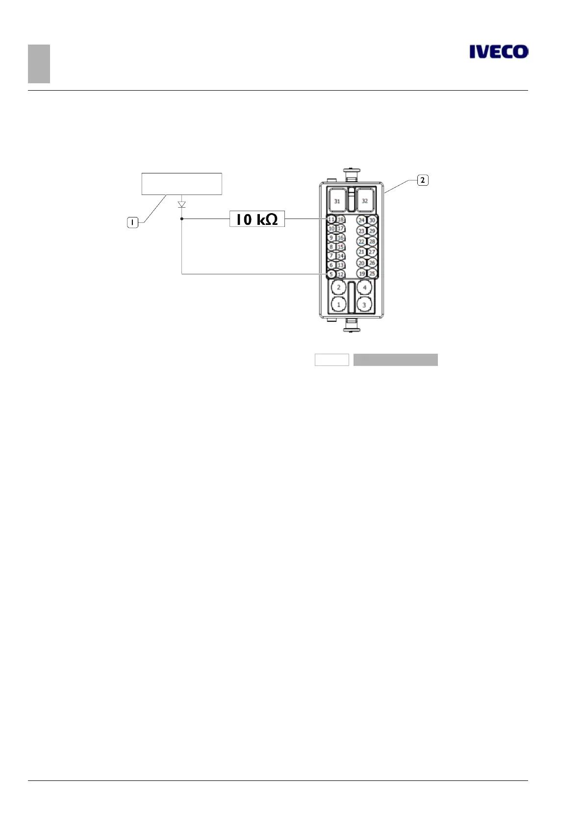
Obligatory insertion of a 10 kOhm pull-up resistor between 72105A / pin 11 (signal K15) and 72105A / pin 05 as outlined in Figure 5.
262160
Figure 5
1. Outfitting 2. Connector 72105A
(3)
The output signal of the side markers may also be extracted from the chassis connector ST38. If necessary, consult Chapter 5.4
–
Para-
graph "Arrangement of side lights (Side Marker Lamps) ".
(4)
For vehicles in the Hi-MATIC version, refer to the indications provided in Annex C (
➠
Page 8)
(5)
Only supported with Cruise Control option.
The resistors must be connected between pin 12 and pin 13. Different functions may be activated depending on the resistor value:
R = 2490 Ohm CC ON: CC stays active, just like the PTO modes (important for vehicles without Cruise Control)
R = 649 Ohm
SET+: the speed increases by +50 revs/min pulse (only when the vehicle is stationary) or adjustment of the CC speed (only at V >
30 km/h)
R = 261 Ohm
SET-: the speed decreases by -50 revs/min pulse (only when the vehicle is stationary) or adjustment of the CC speed (only at V >
30 km/h)
R = 133 Ohm RES: activation of ISC MEMO speed or resuming the stored CC speed

 Loading...