2-60
CHASSIS MODIFICATIONS
D
AILY 4x4
Base - May 2007 Print 603.93.761
Electrical System: Modifications and Drawing-Off Power
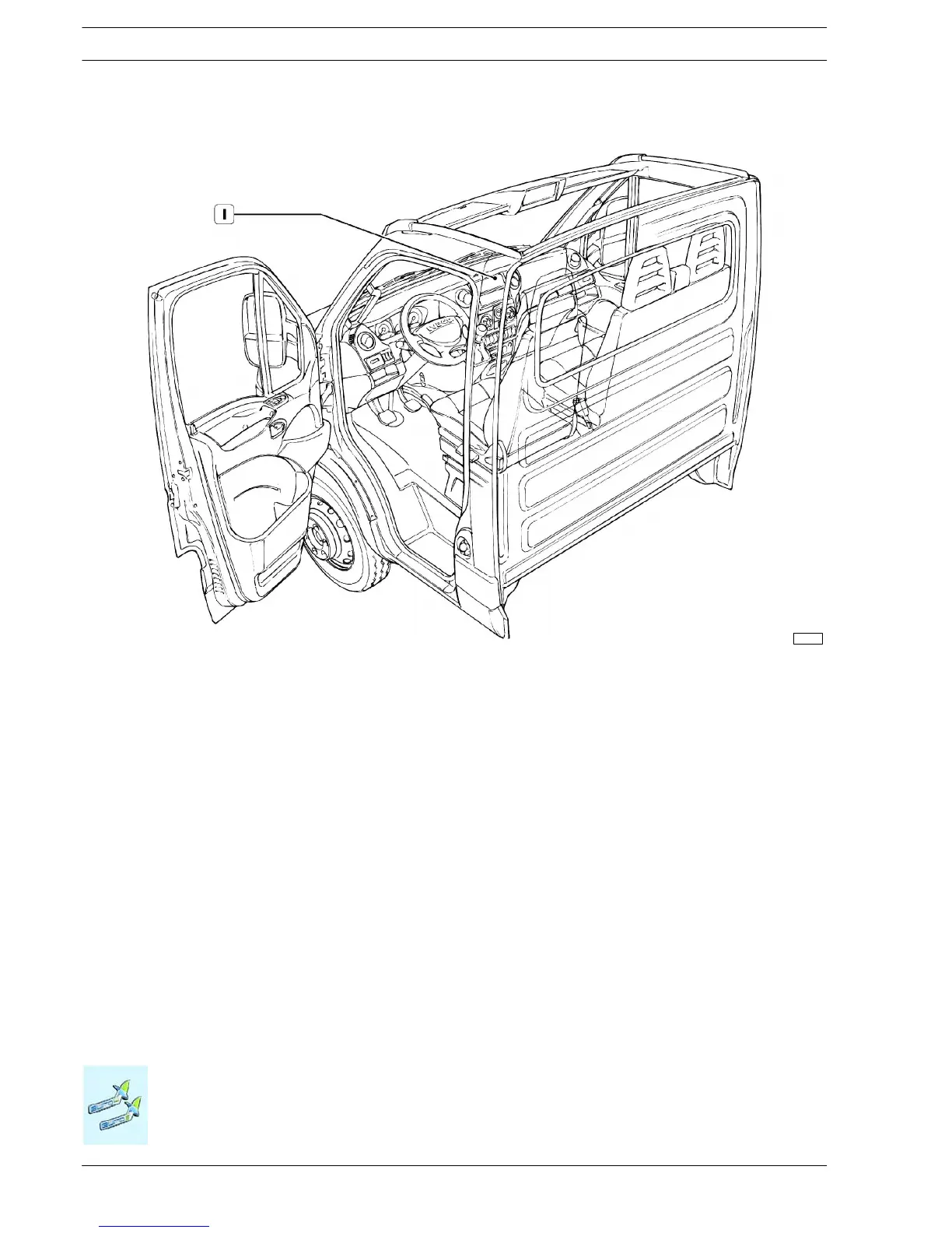
Figure 2.33
1. Location of the CB transceiver unit (City Band)
119358
Two-way systems for GSM/PCS/UMTS mobile phones
Cellular telephone sy stems must be installed using the power system provided in the vehicle. Connect to terminal 30 via a supple-
mentary fuse.
The devices must be legally type- approved an d fixed (not portable). Install t he transmitting part in a flat, dry area separate from the
electronic components of the vehicle, away from humidity and vibrations.
• The SWR must be as close as possible to one. The recommended value is 1.5, while the maximum acceptable value must not
in any case be greater th an 2.
• The AERIAL GAIN values must be as high as possible and ensure sufficient spatial uniformity, normally with deviations from the
average valu e in the order of 1.5dB in the 870-960 MHz band and 2 dB in the 1710-1880MHz band.
• The RADIATED CAB FIELD value must be as low as possible. We su ggest < 1 V/m as a quality target. In any case, the value
must not exceed limits imposed by current European guidelines.
• For this reason, the aerial must always be placed on the outside of the vehicle cab, if possible on a broad metal base fitted as
upright as possible with the connection lead facing downwards, observing the Manufacturer’s installation instructions and warn-
ings.
The ideal location of the antenna is on the front of the cab roof at a distance no less than 30 cm from other antennas.

 Loading...
