Do you have a question about the IWAKI WALCHEM Intuition-6 Series and is the answer not in the manual?
| Model | Intuition-6 Series |
|---|---|
| Type | Controller |
| Input Channels | Up to 6 |
| Input Voltage | 100-240V AC |
| Output | Relay, Analog, Digital |
| Communication Protocols | Ethernet |
| Inputs | Analog, Digital |
| Outputs | Relay, Analog, Digital |
| Enclosure | NEMA 4X |
| Power Supply | 100-240V AC |
| Storage Temperature | -20 to 60°C (-4 to 140°F) |
| Output Channels | 6 |
Details sensor measurement ranges, resolution, and accuracy for various parameters.
Describes electrical specifications for inputs, outputs, and power.
Specifies the instrument's purpose and application in water treatment.
Covers enclosure material, rating, and physical dimensions of the controller.
Lists configurable input/output settings and their allowed value ranges.
Instructions for inspecting the controller and its contents upon arrival.
Guidelines for securely wall-mounting the controller enclosure.
Details for installing the immersible copper sensor for in-tank monitoring.
Procedures for installing the flow-through copper sensor and sample loop.
Procedures for installing the flow-through nickel sensor and sample loop.
General guidelines and specific advice for installing various sensor types.
Explains the meaning of various symbols used in the interface.
Provides crucial safety and wiring guidelines for electrical installation.
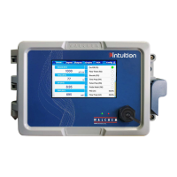
Identifies and describes the physical components on the controller's front panel.
Explains the touchscreen interface, menu structure, and navigation.
Details the meaning and function of icons displayed on the Home screen.
Guides the user through the initial power-up and setup process.
Provides instructions on how to properly turn off the controller.
Describes how to view and manage active alarms on the controller.
Covers configuring, calibrating, and managing sensor and digital inputs.
Details how to program and control relay and analog outputs for various modes.
Explains system settings, security, network, and display configurations.
Allows testing and managing relay outputs in Hand, Off, or Auto modes.
Explains how to view and customize parameter data graphs.
Instructions for connecting the controller to a Local Area Network.
Steps for establishing a direct network connection between the controller and a PC.
Guide to accessing and interacting with the controller's web interface.
Details on displaying and customizing parameter graphs via the web interface.
Procedure for updating the controller's firmware via the network.
Functionality for storing notes and process information within the controller.
How to initiate and perform sensor calibration remotely through the web interface.
Instructions for cleaning copper and nickel sensors to ensure accurate readings.
Guidance on cleaning and calibrating pH electrodes for optimal performance.
Specific causes and corrective actions for copper/nickel sensor calibration problems.
Specific causes and corrective actions for pH sensor calibration problems.
Specific causes and corrective actions for contacting conductivity sensor calibration issues.
Specific causes and corrective actions for electrodeless conductivity sensor calibration issues.
Specific causes and corrective actions for ORP sensor calibration problems.
Specific causes and corrective actions for disinfection sensor calibration problems.
Specific causes and corrective actions for analog input calibration problems.
Specific causes and corrective actions for temperature sensor calibration problems.
Explains various alarm messages and their potential causes and corrections.
Steps to evaluate the performance and condition of a conductivity electrode.
Steps to evaluate the performance and condition of pH/ORP electrodes.
Interprets the status of diagnostic LEDs on various controller boards.
