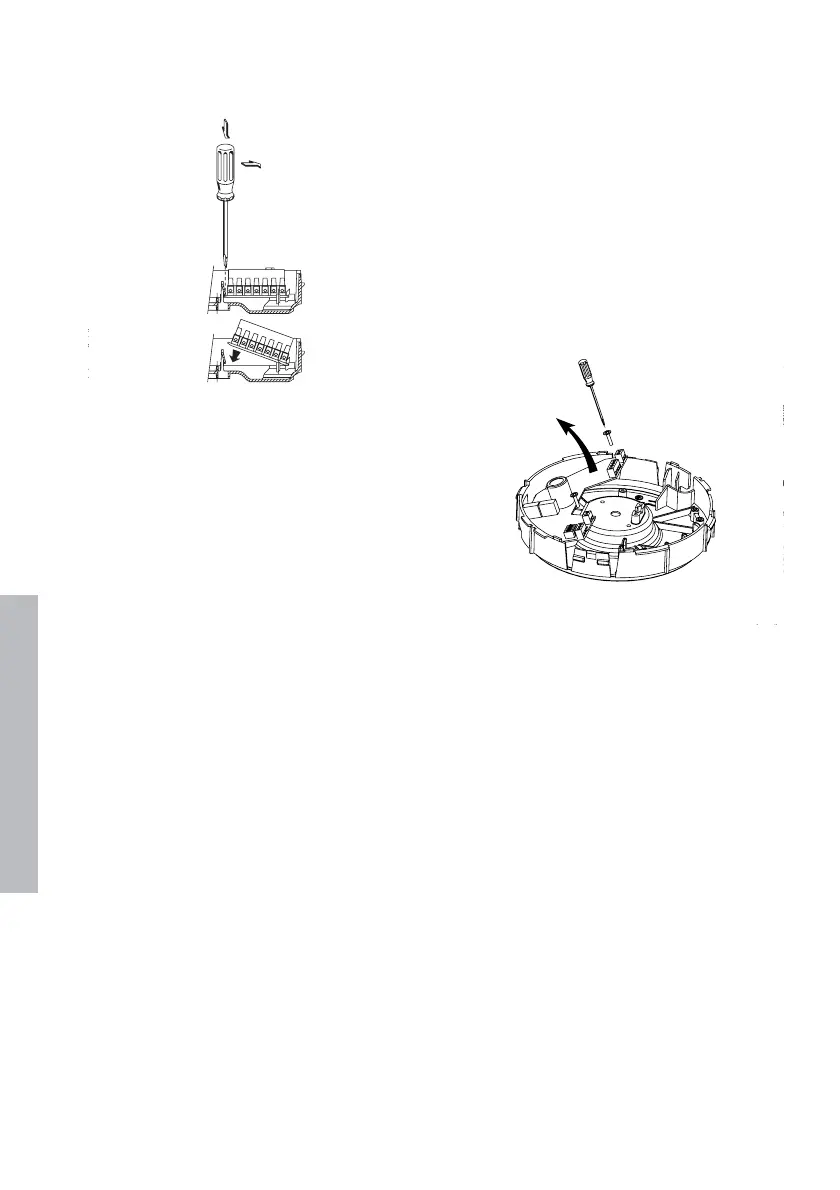
Disassembly of control circuit board (CMLe)
The motor plate must be supported before the circuit
board can be removed. Loosen the two screws. By
tilting the circuit board a little, it will come free from
the click connector on the outer edge of the motor
plate. Then the circuit board can be removed (see
drawing 4).
Assembly of control circuit board (CMLe)
The motor plate must be supported before the circuit
board can be remounted. Place the circuit board in
the two square openings on the outer edge of the
motor plate in such a way that it lies on the two
projections situated on both sides of the opening.
Press the circuit board downwards on the two
mounting points. Align the mounting holes in the
circuit board with the mounting points in the motor
plate. Replace the screws and retighten them.
10