32
7. Technical data
7.1 WHR 950 Specifications
Indication of unit values
Ventilation capacity (pre-settings)
Low position 125m
3
/h at 82 Pa 70 W
Medium position 200m
3
/h at 157 Pa 133 W
High position 350m
3
/h at 300 Pa 320 W
Low position 125m
3
/h at 82 Pa 0.36 A
Medium position 200m
3
/h at 157 Pa 0.62 A
High position 350m
3
/h at 300 Pa 1.45 A
Maximum 450m
3
/h at 200 Pa 1.51 A
Power supply
Supply voltage 230/50 V/Hz
Cos. phi 0,85-0,96 -
Sound capacity (Lw.o=10-12W)
Supply
Low position 125m
3
/h at 8 Pa 57 dB(A)
Medium position 200m
3
/h at 157 Pa 66 dB(A)
High position 350m
3
/h at 300 Pa 75 dB(A)
Exhaust
Low position 125m
3
/h at 82 Pa 47 dB(A)
Medium position 200m
3
/h at 157 Pa 53 dB(A)
High position 350m
3
/h at 300 Pa 70 dB(A)
7.2 General specifications
Air and condensation drain connections: see drawings page 57
Materials
High power exchanger: Polystyrene
Interior: Alu.
Miscellaneous
Thermal efficiency (EPN) 95 %
Weight 50 kg
8. Installation
Installation conditions
In order to determine whether the WHR can be installed in a certain area,
the following aspects must be taken into account:
• The WHR must be installed according to the general and locally appli-
cable safety and installation regulations of electricity and water boards,
and also according to the regulations of this manual.
• The place of installation must be chosen so that there is sufficient room
around the unit for air duct connections, intake and exhaust lines and
in order to carry out maintenance work.
• The following must be available: air duct connections, electrical con-
nection 230 Volt with Perilex wall socket and facilities for condensation
drainage.
• Both the outside air intake duct and the air exhaust duct must be ren-
dered damp proof between the roof/wall passage and the WHR. This
prevents the formation of condensation on the outside of the duct.
•A double walled or insulated roof passage must be fitted in front of the
air exhaust duct. This prevents the formation of condensation between
the roof boarding.
• The air exhaust duct must drain in the direction of the unit.
• The WHR must be installed in a frost-free space. The condensation
water must be drained frost free, using a siphon.
• Do not fit a powered extractor hood to this system.
☞
For the sake of muffling, an acoustic hose (from 1 to 1.5m long and
with a diameter of 180mm) should be fitted to the intake immedi-
ately after the unit.
8.1 Transportation and unpacking
Take care when transporting and unpacking the unit. Ensure that the pack-
aging materials are disposed of in an environmentally responsible manner.
8.2 Inspection upon delivery
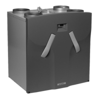
8a. WHR left
Contact your supplier directly in the case of damage or an incomplete
delivery. The delivery includes:
• The WHR, a manual and a bracket.
The WHR is supplied in either "basis" or "bypass" versions: WHR or WHR
B. Both are supplied in a left and right-handed variant: WHR R or WHR L.
Check that you have the right model. Look at the sticker on top of the
WHR and the model plate on the side of the unit.
8b. WHR right
English
 Loading...