EasyManua.ls Logo

J.Schneider AKKUTEC 2412 VdS User Manual

J.Schneider AKKUTEC 2412 VdS
16 pages
To Next Page IconTo Next Page
Page #1 background imageLoading...
Page #1 background image
User manual
AKKUTEC 2412 VdS
Document page 1 / 16
0812G01B02-160422.docx
J. Schneider Elektrotechnik GmbH
Helmholtzstraße13, 77652 Offenburg · Postfach 2327, 77613 Offenburg · Werner-von-Siemens-Straße 12, 77656 Offenburg
Tel +49 (0) 781 206 0 · Fax +49 (0) 781 253 18 · info@j-schneider.de · www.j-schneider.de · Amtsgericht Freiburg HRB 470458
Geschäftsführer: Dipl.-Betriebswirtin (BA) Bettina Schneider · Dipl.-Wirt,-Ing. (FH) Rolf Anti · UST-Ident-Nr. DE142532740
DC-USV
NBPA0812G01***
VdS-Nummer G209169
0786-CPD-20873
page
1. General ...................................................................................................................... 2
1.1 General safety notes
1.2 Short description
2 Transportation and storage ..................................................................................... 3
3 Installation and connection ..................................................................................... 3
3.1 Installation
3.2 Connection
3.3 Connection lead accumulator
3.4 Connection of mains voltage
3.5 Connection load
3.6 Signal contacts
3.7 Circuit diagram
4 Start-Up ..................................................................................................................... 9
4.1 Display and messages
5 Operation .................................................................................................................. 9
5.1 Mains operation
5.2 Back-up operation
5.3 Deep discharge protection
5.4 Accumulator circuit monitoring
5.5 Accumulator test
5.6 Temperature tracking (optional)
5.7 Shut-Down
5.8 Acoustic alarm transmitter (optional)
6 Master/Slave-operation at parallel connection ..................................................... 11
6.1 Connection at Master/ Slave-operation
6.2 Signalisation at Master/Slave-operation:
6.3 Shutdown at Master/Slave-operation
6.4 Configuration Master/Slave
7 Servicing .................................................................................................................. 13
7.1 Testing the lead accumulators
7.2 Exchanging the lead accumulators
8 Decommissioning .................................................................................................... 14
9 Disposal ................................................................................................................... 14
10 Norms and regulations ........................................................................................... 14
11 Technical Data ......................................................................................................... 15
12 Accessories ............................................................................................................. 16
Question and Answer IconNeed help?

Do you have a question about the J.Schneider AKKUTEC 2412 VdS and is the answer not in the manual?

J.Schneider AKKUTEC 2412 VdS Specifications

General IconGeneral
Input Voltage230V AC
Output Voltage24V DC
Output Current12A
VdS CertificationYes
Protection ClassIP20

Summary

General Information and Safety

General Safety Notes

Safety instructions must be read and observed prior to installation or use. Claims may be lost if not followed.

Short Description

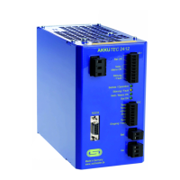
Overview of the accumulator-buffered DC supply and its key features.

Transportation and Storage Guidelines

Installation and Connection Procedures

Installation Requirements

Proper mounting and ventilation are crucial for cooling and air circulation.

Electrical Connection

Connecting the unit to power sources, including mains and accumulators.

Lead Accumulator Connection

Specific instructions for connecting lead accumulators, including series connection.

Mains Voltage Connection

Connecting the unit to the mains supply, emphasizing safety and grounding.

Load Connection

Connecting the load to the DC output, observing polarity.

Signal Contacts Overview

Description of signal contacts for forwarding status to a central unit.

Circuit Diagram

Visual representation of all connections and terminal assignments.

Start-Up and Initial Operation

Display and Messages

Explanation of the four LEDs indicating the unit's status.

Unit Operation Modes

Mains Operation

Indicates operation when mains voltage is present and stable.

Back-up Operation

Unit switches to battery power when mains voltage fails or drops.

Deep Discharge Protection

Prevents irreversible damage to accumulators by disconnecting loads.

Accumulator Circuit Monitoring

Tests the accumulator circuit for interruptions or high resistance.

Accumulator Test

Cyclic test to assess battery health and internal resistance.

Temperature Tracking (Optional)

Adjusts charging voltage based on ambient temperature for optimal battery life.

Shut-Down Function

Early interruption of buffer operation to prevent deep discharge.

Acoustic Alarm Transmitter (Optional)

Emits an acoustic warning signal for general errors.

Parallel Master/Slave Operation

Connecting Master and Slave Units

How to connect two units in parallel for increased power or redundancy.

Signalisation in Master/Slave Mode

How signal contacts indicate status in parallel operation.

Master/Slave Shutdown

Procedures for shutting down units in parallel configuration.

Master/Slave Configuration

Setting up units as Master or Slave for parallel operation.

Servicing and Maintenance

Testing Lead Accumulators

How to test the buffering capability of lead accumulators.

Exchanging Lead Accumulators

Procedures for safely removing and installing lead accumulators.

Decommissioning Procedures

Disposal Guidelines

Norms and Regulations Compliance

Technical Specifications

Available Accessories