Maintenance manual for sunray hfc4da1-2c china-IV diesel engines
150
11.
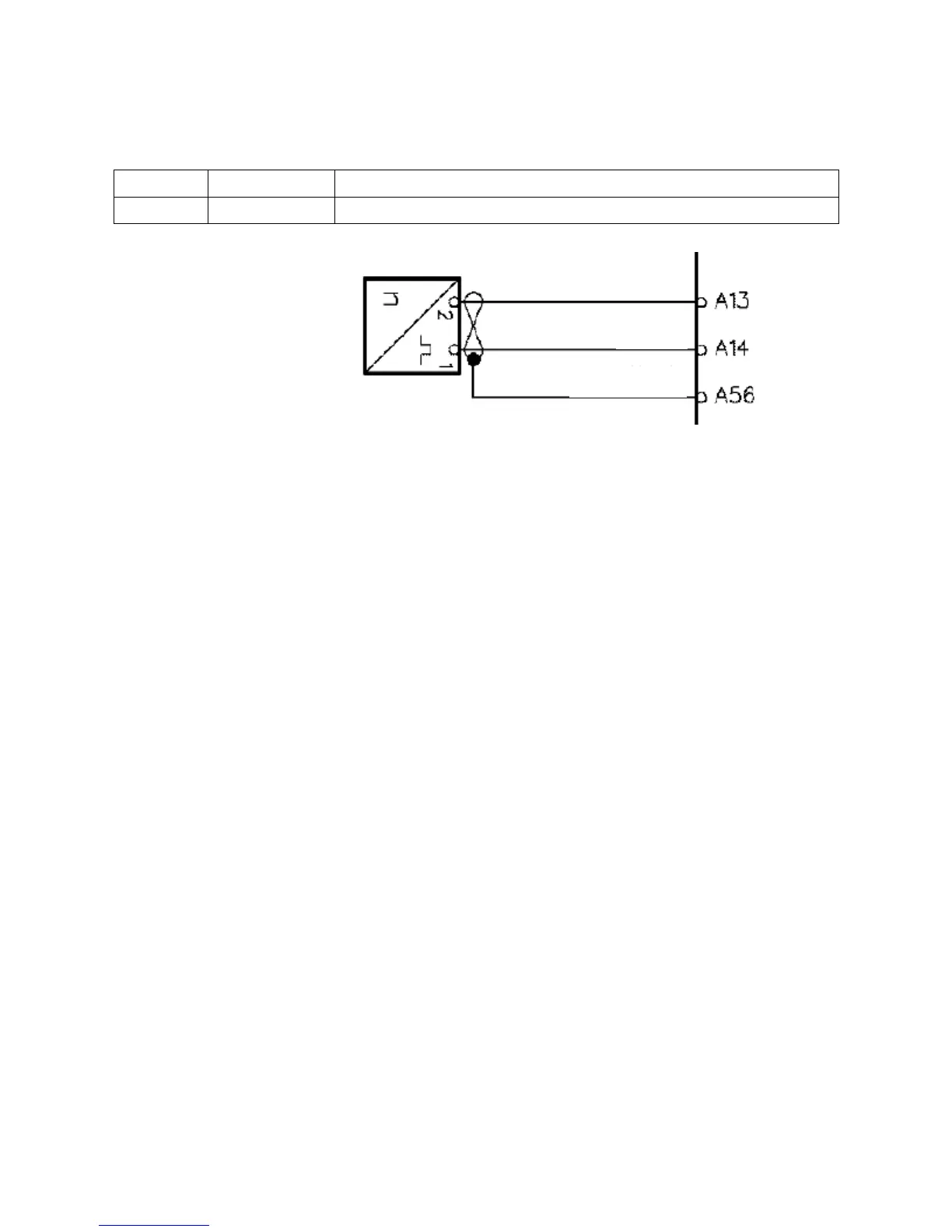
DTC P0335 No signal from crankshaft sensor
P0336 False signal from crankshaft sensor
Diagnosis Hint: The signal of crankshaft position (CKP) sensor is used for indicating the rotary speed and position of
crankshaft. The CKP sensor shall generate an AC voltage of different amplitude and frequency. The frequency relies
on the rotary speed of crankshaft and the output AC voltage relies on the crankshaft position. The CKP sensor shall
coordinate with a 58X variable reluctance rotor fixed on the crankshaft. The ECU can synchronize the timing control
for fuel injectors according to the input signals of CKP sensor and camshaft position sensor. The CKP sensor can also
be applied for testing misfire and tachometer indication. The signal circuit and the low reference voltage circuit of
CKP sensor are directly connected to ECU. The shielded and grounded circuit should be grounded. In addition, when
the 1
st
and the 4
th
cylinders are at TDC, the CKP sensor shall also send a signal to ECU. The ECU shall monitor the
signals of CKP sensor and camshaft position sensor to determine whether the 1
st
cylinder is in compression stroke or
not. The circuits between CKP sensor and ECU include:
Signal circuit of CKP sensor
Low reference voltage circuit of CKP sensor
Shielded and grounded circuit
If the number of crankshaft position pulses sent out by the CKP sensor detected by the ECU is incorrect, the DTC
shall be generated.
Diagnosis Hint: There is failure in camshaft position sensor circuit.
CKP sensor variable reluctance rotor is dislocated or incorrectly installed.
Large crankshaft end play leads to dislocation of variable reluctance rotor.
There is blockage between CKP sensor and variable reluctance rotor.
Check connectors of CKP sensor and ECU for any corrosion.
Prior to maintenance, all fragments should be removed from the connector surfaces. Prior to diagnosis or replacement,
please check the connector gaskets to ensure they are properly installed to avoid ingress of any pollutant.
z Poor terminal connection – Check the harness connector for any loose terminal, mismatching, damaged keeper,
improper form or damage, poor contact between terminal and wire. Check if the matched terminal is adopted.
Check if the test tension is appropriate.
z Harness damage – Check the harness for any damage. If the harness appears normal, observe the indication on
the diagnostic tool while moving relevant connector and harness of the sensor. If the indication changes, there
must be failure in that part.
Wheel speed sensor
Signal
Ground
Shielded wire
 Loading...