EasyManua.ls Logo

JAI AD-130GE User Manual

JAI AD-130GE
87 pages
To Next Page IconTo Next Page
Page #1 background imageLoading...
Page #1 background image
1036E-1201
AD-130GE
Digital 2CCD Progressive Scan
Multi-Spectral Camera
Document Version: 1.1
AD-130GE_Ver.1.1_Mar2012
User's Manual

Table of Contents

Question and Answer IconNeed help?

Do you have a question about the JAI AD-130GE and is the answer not in the manual?

JAI AD-130GE Specifications

General IconGeneral
Sensor TypeCMOS
Resolution1296 x 966
InterfaceGigE Vision
Dynamic Range60 dB
Bit Depth8/10/12-bit
Lens MountC-mount
Operating Temperature0°C to +45°C
Power Supply12-24 VDC

Summary

Introduction

Camera Operation

1. General

Overview of the digital 2-CCD progressive scan multi-spectral camera AD-130GE.

3. Main Features

4. Locations and Functions

4.1. Locations and Functions

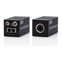
Identifies physical connectors, ports, and components on the camera.

5. Pin Configuration & DIP Switch

5.1. 12-pin Multi-connector (DC-in/GPIO/Iris Video)

Details the pinout for the 12-pin Hirose connector.

5.2. Digital Output Connector for Gigabit Ethernet

Specifies the pin assignment for the RJ-45 Gigabit Ethernet connector.

5.3. 6-pin Multi-connector (LVDS IN and TTL IN/OUT)

Details the pinout for the 6-pin Hirose connector.

5.4. DIP Switches

6. System Configuration

6.1. System Connection

Describes methods for connecting the AD-130GE to a PC.

6.3. Sync Mode

7. Inputs and Outputs Interface

7.1. Overview

Introduces the GPIO module, LUT, Pulse Generators, and 12-bit counter.

7.2. Opto-isolated Inputs/Outputs

7.3. Input and Output Circuits

7.3.2 Trigger Input

7.4. GPIO Inputs and Outputs Table

7.5. Configuring the GPIO Module

7.5.3 GPIO Interface in GenICam Standard

10. Functions (Conforming to GenICam SFNC 1.3)

10.1. Acquisition Function

Covers controls for acquisition, trigger, and exposure.

10.1.1 Basic Image Acquisition Flow

Outlines the fundamental commands for acquiring images.

10.1.2 Acquisition Mode

10.1.2.1 Single Frame

10.1.2.2 Continuous Mode

10.2. Trigger Control

10.3. Exposure Control

10.4. ActionControl

10.5. Operation Mode

10.5.1 The Exposure Timing When the Trigger Pulse is Input

10.5.2 Continuous Mode

10.5.3 Edge Pre-Select (EPS) Trigger Mode

10.5.4 Pulse Width Control (PWC) Trigger Mode

10.5.5 Smearless Mode

10.5.5.1 Sync=Sync, LVAL Async, Smearless Enable=True, EPS Trigger

10.5.5.2 Sync Mode=Sync, LVAL Async, Smearless Enable=True, PWC Trigger

10.5.6 Reset Continuous Trigger (RCT) Mode

10.5.7 Sequential Trigger Mode (EPS)

10.5.7.2 Initial Settings

10.5.8 Delayed Readout EPS and PWC Modes

10.5.9 Multi ROI Mode (Multi Region of Interest)

10.5.9.2 Initial Parameters

10.6. Operation Mode and Functions Matrix

10.6.1. Sync Mode = SYNC

Matrix showing operation modes under SYNC mode.

10.6.2 SYNC Mode = Async

Matrix showing operation modes under ASYNC mode.

11. Other Functions

11.1.2 Electronic Shutter

Exposure Time Abs (GenICam Standard)

Programmable Exposure

11.1.3 Shading Correction

11.1.4 White Balance

11.1.5 Blemish Compensation

11.1.6 Test Signal Generator

11.2. Control Tool Screen

11.2.2 Feature Properties (Guru)

12. External Appearance and Dimensions

13. Specifications

13.2. Specification Table

Appendix

1. Precautions

Safety precautions for handling and operating the camera.

Related product manuals